8.7 DESIGN OF PROPELLANT TANK PRESSURANT DIFFUSERS
The main function of a pressurant diffuser is to introduce the pressurant gases evenly into the propellant tank at a desired direction and velocity. The gases are usually injected in a plane near the tank forward end, at a right angle to the tank and vehicle axes. This will minimize disturbances at the pressurant-propellant interface. Figure 8-16 presents some typical propellant tank pressurant diffuser designs. A radialtype diffuser, located at the tank axis, is used for the fuel tank. This arrangement permits a simple, lightweight diffuser design. However, the reversed ellipsoidal common bulkhead at the forward end of the oxidizer tank requires a ringtype diffuser, consisting of many individual diffusing nozzles located at the circumference of the tank.
The pressurant enters the tank at a temperature level depending on the source, such as a LOX heat exchanger. In some cases, this may not be the optimum temperature for critical struc- tural members. In these cases, a separation tube (Hilsch tube) may be combined with the diffuser. Without moving parts, it operates on the principle of saparating the higher energy molecules from those with lower energy. Temperature spreads of or more can be obtained, depending on construction and available pressure drop. Advanced configurations have been developed by the AiResearch Manufacturing Ch. In a LOX/ hydrogen system with common bulkhead, the device may be used to direct the cold stream toward the bulkhead, thus lowering the temperature differential and resultant heat transfer across it.
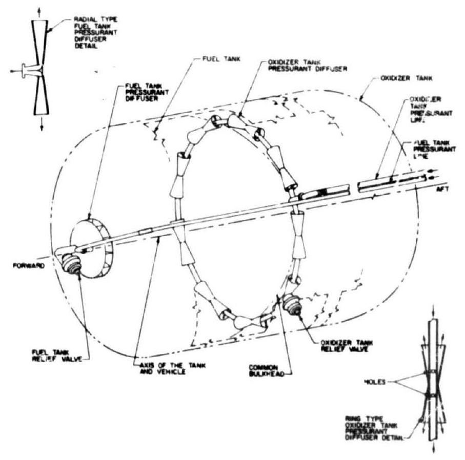 Figure 8-i6.-Typical designs of propellant tank pressurant diffusers.