As a rule, the wall thickness of propellant tanks is first calculated from stresses caused by internal pressure loads and discontinuities. Then the design is checked for other loads. If the wall thickness of a pressure vessel is small compared to the radii of wall curvature (t/r≤1/15),
and offers no resistance to bending, the wall is subjected only to direct or hoop-membrane stresses, assumed to be uniformly distributed over the thickness. However, if any discontinuity is present along the wall, such as an abrupt change in radius of curvature or wall thickness, discontinuity and bending stresses are added. At a sufficient distance from the juncture between tank ends (sphere or ellipsoid) and cylindrical shell (where interaction does not occur), the maximum stress in the tank wall due to internal pressure is calculated using the hoopmembrane stress formula only.
Figure 8-6 identifies the major tank elements. In an optimum tank design, the wall thickness varies according to a combination of local membrane, bending, and discontinuity stresses. This is especially true for the spherical and ellipsoidal tank ends. The structural calculation methods for volume, wall thickness, wall surface area, and weight of various tank shapes will now be discussed. The following general terminology is used:
pt=SW=ρ=E=V=eW= maximum tank working pressure, psig maximum allowable working stress of the tank construction material, psi density of the tank construction material, lb/in3 modulus of elasticity, psi Poisson’s ratio weld efficiency
Figure 8-6.-Nomenclature of principal tank elements.
where a= nominal radius of the tank, in
(2) Wall thickness, in, required to withstand membrane stresses from internal tank pressure:
tS=2Swewpta(8-11)
(3) Wall surface area, in 2 :
AS=4πa2(8-12)
(4) Weight, Ib:
WS=4πa2tSρ(8-13)
(5) Critical pressure due to external loading, psi . When the external pressure is higher than the internal tank pressure, the pressure differential across the tank wall may cause the tank to buckle.
Note that the spherical end is a special case of ellipsoidal end, in which the major halfdiameter, a, equals the minor half-diameter, b.
(1) Volume:
Ellipsoidal tank end volume, in 3 :
Ve=32πa2b(8-15)
Spherical tank end volume, in 3 :
Vs=32πa3(8-16)
where
a= elliptical tank end major half-diameter, in = radius of the cylindrical tank section
b= elliptical tank end minor half-diameter, in
(2) Wall thicknesses considering combined membrane, discontinuity, and local bending stresses caused by internal tank pressure pt. An equivalent wall thickness, which is an average value of knuckle-and-crown thickness, may be
used to calculate the weight of the tank ends.
where
k= tank end ellipse ratio =a/b;k=1 for a spherical end
R= tank end crown radius, in =ka;R=a for a spherical end
K= stress factor, a function of the ellipse ratio k. Figure 8.7 presents a K versus k curve for combined membrane, discontinuity, and local bending stresses
tk= wall thickness at the knuckle, in
tcr= wall thickness at the crown, in
te= equivalent wall thickness of an ellipsoidal tank end, in
ts= equivalent wall thickness of a spherical tank end, in
tc= wall thickness of a cylindrical tank section, in
(3) Wall surface area:
Ellipsoidal tank end surface area, in 2 :
Ae=a2+2eπb2ln[(1−e)(1+e)](8-23)
Spherical tank end surface area, in 2 :
AS=2πa2(8-24)
Figure 8-7.-Ellipse ratio k versus knuckle stress factor K, compression stress −K, and parameter E′. (From ARS paper, "Design Criteria and Analyses for Thin-Walled Pressurized Vessels and Interstage Structures," by T. J. Hart.)
where
e= eccentricity =aa2−b2=1−k21
(4) Weight:
Ellipsoidal tank end weight, lb:
We=2kπa2teE′ρ(8-25)
Spherical tank end weight, lb:
WS=2πa2tSρ(8-26)
where
E′= design factor =2k+k2−11lnk−k2−1k+k2−1
(see fig. 8-7)
(5) Critical pressure due to external loading, psi:
For an ellipsoidal tank end, it may be approximated as
pcre =R2Cb2Ete2(8-27)
For a spherical tank end
pcrs=a20.342Ets2( approximately )(8-28)
where
Cb= buckling coefficient, a function of R/te. ranging from 0.05 to 0.10
where
a = radius, in
Ic= length, in
(2) Wall thickness, in, required to withstand membrane stresses due to internal tank pressure:
tc=SWeWpta(8-30)
(3) Discontinuity stresses.-The discontinuity at the juncture between the cylindrical tank section and the tank ends will cause bending and shear loads along the cylindrical circumference at the juncture, and the adjacent areas. These discontinuity stresses are superimposed upon the membrane stresses and comprise: (a) axial bending stress; (b) hoop bending stress; (c) additional hoop stress due to the shear load; (d) shear stress. Discontinuity stresses fade out rapidly, so that they become negligibly small a short distance from the juncture. Detail analyses of discontinuity stresses can be found in standard textbooks. In general, buildup of wall thickness of less than 0.5tc, near the juncture, will suffice for most designs, with only small weight penalty.
(4) Wall surface area, in 2 :
The following design data are specified for the A-4 stage propulsion system, which employs a cylindrical propellant tank section with ellipsoidal ends (preliminary layout shown in fig. 3-10).
Required design volume of the oxidizer tank,
Vto=120ft3
Maximum oxidizer tank working pressure,
pto=180psia
Required design volume of the fuel tank,
Vtf=143.5ft3
Maximum fuel tank working pressure, ptf =170 psia
Internal radius of the cylindrical tank section,
Weld efficiency, eW=100 percent.
Determine the following:
(a) Required internal tank dimensions
(b) Required thickness of the tank walls at various sections, considering internal pressure loads, discontinuity, and local bending stresses
(c) Approximate weight of the tankage
(d) Critical external loading pressures, using a buckling coefficient, Cb=0.10 for the tank ends
(a) Since the oxidizer tank consists of two ellipsoidal ends without a cylindrical section, equation (8-15) may be applied:
Vto =32×2πa2b
We rearrange to obtain the minor elliptical half-diameter of the tank ends:
b=2×2πa23×Vto=4×π×(41)23×120×1728=29.4in
The tank end ellipse ratio:
k=ba=29.441=1.395
Since we use an ellipsoidal end of the same proportion at the fuel tank top, the fuel tank volume may be treated as the volume of a cylindrical tank section with the length lc. From equation (8-29), the volume of the fuel tank:
To summarize the internal dimensions of the tankage:
a=41in,b=29.4in,k=1.395,lc=46.9in
(b) We assume that certain missions of the A-4 vehicle require it to be man rated. From equations (8-6) and (8-7), the maximum allowable working stresses are derived:
We use the lower value of 34560 psi .
From figure 8-6, the tank end stress factor K of the combined stresses is 0.80 for an ellipse ratio k of 1.395 . From equation (8-17), the re-
quired wall thickness at the knucklo of the oxidizer tank end
tko=SwKpta=345600.80×180×41=0.171in
From equation (8-18), the required wall thickness at the crown of the oxidizer tank end
tcro=2SwptR=2×34560180×1.395×41=0.149in
From equation (8-19), the equivalent wall thickness of the oxidizer tank end
teo=2(tkO+tcrO)=2(0.171+0149)=0.16in
NOTE: In some designs, weight has been saved by taking advantage of the fact that the bulkhead common to both tanks is subject to a relatively small differential pressure in operation. Such systems, however, require more elaborate pressurization and loading systems including interlocks. In case of malfunction, the coumon bulkhead may suffer serious damage.
The required wall thickness at the knuckle of the fuel tank end:
tkf=ptotkoptf=1800.171×170=0.162in
The required wall thickness at the crown of the fuel tank end:
tcrf=ptotcroptf=1800.149×170=0.141in
The equivalent wall thickness of the fuel tank end:
tef=2(tkf+tcrf)=2(0.162+0.141)=0.152
From equation (8-30), the required wall thickness of the cylindrical tank section:
tc=SWptfa=34560170×41=0.202in
Provide a buildup of 0.4tc on the cylindrical tank section wall near the juncture to allow for discontinuity stresses:
tcj=tc+0.4t=0.202+0.4×0.202=0.283in
To summarize:
tko=0.171in,tcro=0.149in,teo=0.16intkf=0.162in,tcrf=0.141,tef=0.152intc=0.202in,tcj=0.283in
(c) From equation (8-25), the weight of the oxidizer tank end:
Weo=2kπa2teoE′ρ
From figure 8-7, E′ is 4.56 , for k=1.395 :
Weo=2×1.395π(41)2×0.16×4.56×0.101=139.5lb
The weight of the fuel tank end:
Wef=teoWeotef=0.16139.5×0.152=132.8lb
From equation (8-32), the weight of the cylindrical tank section:
Wc=2πalctcρ=2×41×46.9×0.202×0.101=246.4lb
Add 4 percent of overall tankage weight for local wall thickness buildups, to allow for welded joints, discontinuity stresses, etc., and for tolerances during fabrication.
Approximate overall weight of the tankage (less accessories):
Axial Compressive Loading on the Cylindrical Tank Section
In integrated propellant tank designs (figs. 8-2 and 8-3), the cylindrical tank section must withstand large axial compressive loads during vehicle handling and operation. If the tank is not pressurized, i.e., if tank pressure = anibient pressure, the critical axial compressive stress for an unstiffened cylindrical tank may be calculated as
Sc=[9(atc)1.6÷0.16(lctc)1.3]E(8-35)
where Sc= critical axial compressive stress, psi. This is the axial compressive stress that will cause the tank to buckle
One method of increasing the axial loadcarrying ability of a cylindrical tank section with minimum weight penalty is to pressurize the tank. This is known as pressure stabilization. Internal pressure will raise the critical buckling stress of a tank; or it may be used to counterbalance an axial compressive load Fa,lb, where
Fa=πa2pt(8-36)
Pressurization will also reduce tank failures from very large bending loads. However, if the pressure is ever permitted to drop below a value necessary to carry the axial and bending loads, the tank will collapse and the vehicle will probably be damaged beyond repair.
An alternative method of increasing the external load-carrying ability of a cylindrical tank is to make it self-supporting. This involves stiffening the cylindrical skin by means of longitudinal and circumferential members, or honeycomb structures. The members may be either separate stiffeners welded to the tank wall, or may be made integral with the wall by machining or chemically milling a thicker sheet.
For the A-4 stage tankage, calculate:
(a) Critical axial compressive load of the cylindrical tank section with no internal pressure.
(b) Required internal tank pressure to offset an axial compressive load of 100000 pounds with no compressive stress on the cylindrical tank section.
The critical axial compressive load of the cylindrical tank section:
Fc=Sc×2πatc=20360×2π×41×0.202=1060000lb
From the results it is obvious that the A-4 stage tankage is capable of withstanding a substantial axial compressive load without internal pressurization.
(b) From equation (8-36), the required internal tank pressure:
When a loaded propellant tank is subject to an impact force, a water-hammer effect occurs within
the tank. This effect produces a surge of the tank internal pressure. For very short impacting times (less than 1.2×10⁻³sec ), the following correlations are established for cylindrically shaped propellant tanks:
c=1+[Etc2.5Epa(1−0.8v)]ps=πa2gcw˙(8-37)
where
pS= pressure surge due to the impact, psi
w˙= equivalent flow rate of the propellant due to the impact, lb/sec
a = radius of the cylindrical tank, in
tc= wall thickness of the cylindrical tank, in
g= gravitational constant, 32.2ft/sec2c= acoustic velocity of the restrained propellant, in/sec
c′= free acoustic velocity of the propellant, in/sec
Ep= compressive modulus of elasticity of the propellant, psi
E= modulus of elasticity of the tank construction material, psi
v= Poisson's ratio of the tank construction material
In many prepackaged liquid applications, the propellant tankage is required to withstand certain impact loads, as specified by the height of the drop tests. The details of estimating tank pressure surges from a free-fall impact are illustrated by sample calculation (8-5).
The following data are given for the cylindrical fuel tank of a prepackaged storable liquid propulsion system:
Fuel, N2H4
Fuel density, ρp=63.17lb/ft3
Compressive modulus of elasticity of the fuel, Ep=6.06×10⁵
Free acoustic velocity of the fuel, c′=80100 in/sec
Tank construction material, aluminum alloy 6066-T6
Modulus of elasticity of the tank construction material, E=10.4×10⁶
Poisson's ratio of the tank construction material, v=0.36
Radius of the cylindrical tank, a=4 in
Length of the cylindrical tank, lc=50in
Wall thickness of the cylindrical tank, tc=0.167in
For a tank falling in direction of its longitudinal axis, estimate:
(a) Tank pressure surge due to the impact after a 6-foot free drop
(b) Tank pressure surge due to the impact after a 20 -foot free drop
(a) For a 6 -foot free drop the final velocity at impact:
V=2gh=2×32.2×6=19.65fps
This yields an equivalent propellant flow rate due to impact of
W˙=ρpπa2V=63.17×π×(124)2×19.65=434.5lb/sec
From equation (8-38), the acoustic velocity of the restrained fuel
Impact time delay in the tank:
clc=4310050=1.16×10⁻³sec( i.e., <1.2×10⁻³sec)
Using equation (8-37), we obtain the tank pressure surge due to impact after a 6 -foot free drop:
pS=πa2gcW˙=π×(4)2×38643100×434.5=964psi
(b) After a 20 -foot free drop, the final velocity at impact is
V=2gh=2×32.2×20=35.9fps
The equivalent propellant flow rate due to impact:
w˙=ρpπa2V=63.25×π×(124)2×35.9=792.5lb/sec
The tank pressure surge due to impact after a 20 -foot free drop:
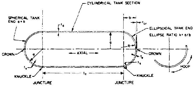 Figure 8-6.-Nomenclature of principal tank elements.
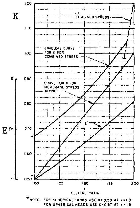 Figure 8-7.-Ellipse ratio versus knuckle stress factor , compression stress , and parameter . (From ARS paper, "Design Criteria and Analyses for Thin-Walled Pressurized Vessels and Interstage Structures," by T. J. Hart.)