7.6 DESIGN CONSIDERATIONS FOR FLUIDFLOW CONTROL COMPONENTS
By their very nature, liquid propellant rocket engines use many control elements for regulating and measuring of fluid flows, such as valves, pressure regulators, and flowmeters. Some of the design considerations governing these components are discussed below.
Basic Flow Characteristics of an Ideal Fluid
Fluids, by definition, include both liquids and gases. A liquid is an incompressible fluid which is characterized by a tendency to retain a fixed density or volume; but not shape. A gas is a compressible fluid which has no tendency to either a definite shape or volume. Its density or volume will vary according to the basic gas laws (eqs. 1-9, 1-12, and 1-13). In general, the same fundamental laws of force, mass, and velocity apply to matter in all forms, and thus are also applicable to the flow of fluids.
The analysis of fluid-flow controls may be simplified by initially assuming ideal conditions. For the calculation of physical dimensions and functional characteristics of specific control components, the results can then be modified by additional assumptions and empirical factors, which often are the result of extensive testing. A frictionless (zero viscosity), incompressible fluid which is nonturbulent and loses no mechanical energy as heat is referred to as an ideal fluid. For steady, ideal-fluid flow in a closed conduit, Bernoulli's energy equation applies:
DESIGN OF CONTROLS AND VALVES
Assuming , and rearranging the expressions, we obtain
In conformance with the continuity law of fluid flow
and
where
conduit at sections 1 and 2. in
The above basic fluid-flow characteristics can be used to measure or sense the flow rate in flow control systems. An accurately sized restriction, such as an orifice, nozzle, or venturi, is inserted in the conduit. Pressure taps are provided for reading the static pressure and at the inlet (sec. 1) and at the minimum area of the restriction (sec. 2). If the flow areas , and the fluid density are known, the flow velocities and , and the flow rate can be calculated with the aid of equations (7-3), (7-4), and (7-5). The venturi or orifice meter should be preceded by a straight length of pipe equivalent to at least 10 times its diameter for repeatable results. For liquid flows, this flow-measuring method is fairly accurate, if friction losses are compensated for by the velocity coefficient . For gaseous flows, however, pressure and temperature have a significant influence on the density of the fluid and must be taken into account for calculations.
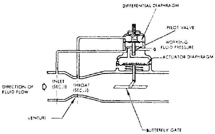 Figure 7-18.-Schematic of a typical closed-loop, fluid-flow control system.
Figure 7-18 is the schematic of a typical closed-loop fluid-flow control system, in which the static pressure differential across a venturi is sensed and used to control fluid flow. The flow is regulated by means of a butterfly gate which is positioned by a fluid-powered actuator diaphragm. The working fluid pressure to the diaphragm is controlled by a pilot valve. Its position in turn is controlled by the pressure differential between venturi inlet (sec. 1) and throat (sec. 2). Because of the dynamic characteristics of the venturi sensing ports, diaphragms, springs, butterflies, and other parts, the relationship between flow rate and venturi pressure differential ( ) is not exactly linear. However, theoretical analyses usually permit good approximations of these dynamic functions. The empirical factors thus obtained will permit design calculations resulting in a reasonable degree of control accuracy. Flow-bench calibrations, including adjustments of, for instance. spring forces, serve to further increase this accuracy. The control of fluid flow and pressure by means of orifices and regulators will be further discussed in subsequent sections.
Sample Calculation (7-1)
The following data are given for a horizontal venturi meter, measuring liquid oxygen flow:
Venturi inlet diameter, in Venturi throat diameter, in Venturi flow velocity coefficient, Pressure differential between inlet and throat Density of LOX, Determine flow rate .
Solution
From equation (7-5):
Substitute this into equation (7-3):
Substitute this into equation (7-4):
Real Fluid Flows Involving Pressure Drops
All real fluids possess the physical property of viscosity; i.e., they offer resistance to shear stresses. The viscosity of the fluid directly affects friction. The basic correlation is given by Newton's law of viscosity (see fig. 7-19):
where
area of the surface in consideration, viscosity of the fluid, (viscosity conversions:
velocity of a fluid particle at the surface in consideration, distance from the point where the velocity of a fluid particle is zero, to the surface in consideration, ft rate of angular deformation of the fluid When a fluid is forced to flow through a closed conduit, its flow is laminar or nonturbulent below certain "critical" velocities. In a laminar flow, the fluid moves in layers, or laminae, one layer gliding smoothly over an adjacent layer, with only a molecular interchange of momentum. The velocity of the fluid is greatest at the center of the conduit and decreases sharply to zero at the conduit wall. As the flow velocity is increased above the "critical" point, the flow becomes turbulent. In turbulent flow an irregular random motion of the fluid exists, in directions transverse to the direction of the main flow. The turbulent flow velocity distribution is more uniform across the conduit than with laminar flow. Even in turbulent flow there is always a thin layer at the conduit wall, the boundary layer, which moves as a laminar flow.
Experiments and theoretical considerations have shown that the Reynolds number, of a given fluid flow can be used as a criteria to indicate whether a flow is laminar or turbulent.
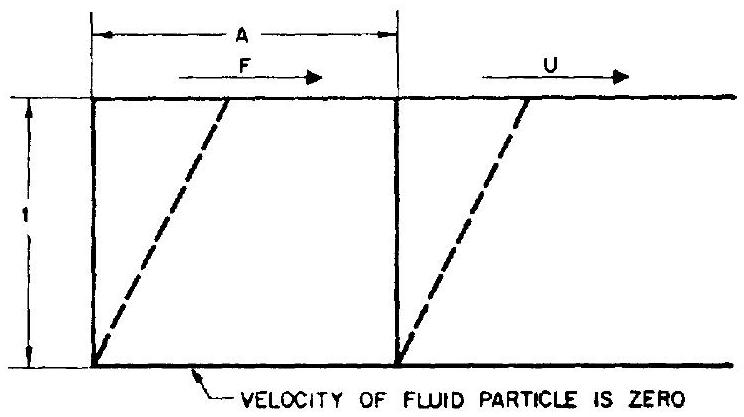 Figure 7-19.-Angular deformation of a real fluid.
( , where equivalent diameter of the conduit, flow velocity, fluid density, ; and fluid viscosity, .) For most calculations, it is assumed that the flow is laminar for Reynolds numbers less than 1200, and turbulent for Reynolds numbers greater than 1200.
Real fluid flows always involve friction caused by rubbing of the fluid particles against one another and against the conduit wall. Consequently, there is a loss of energy; i.e., drop in pressure in the direction of the flow. This energy loss is converted into heat energy. The heat thus produced may be entirely absorbed by the fluid, in one extreme case (adiabatic flow), or it may be entirely dissipated through the conduit wall, in the other extreme (constanttemperature or isothermal flow). Generally-at ambient temperature-the flow of liquids and gases through pipes is assumed to be isothermal. However, adiabatic flow is assumed to take place in nozzles, orifices, short tubes, and valves through which the fluid is moving at high velocities.
The pressure drop ( psi ) of a fluid flowing in straight conduits (ducts or tubes) in a horizontal position can be estimated by equation (7-7). This is essentially the same as equation (4-32), except for the dimensions.
where length of the conduit, in density of the fluid, flow-velocity of the fluid, fps equivalent diameter of the duct or tube, in
Equation (7-7) is valid for laminar or turbulent flow of any incompressible fluid in ducts or tubes. With suitable restrictions it may also be used when compressible fluids are being handled. The density of compressible fluids changes considerably as a function of pressure; therefore, if the pressure drop between two points is great, density and velocity will change appre- ciably. Also, there will be a slight change in the friction factor. Consequently, it is recommended that equation (7-7) be used with compressible fluids only where the pressure drop p is less than 10 percent of the fluid static pressure at the outlet point. To calculate higher pressure drops of compressible fluids, other methods should be used.
If the flow is laminar ( ), the friction factor is a function of the Reynolds number, and can be arrived at by Poiseuille's equation for laminar flow
When the flow is turbulent ( ), the friction factor depends not only upon the Reynolds number but also upon the roughness of the duct or tube walls. The friction factors of turbulent flows may be found by means of the Moody diagram shown in figure 7-20. The dimensionless term, "relative roughness" ( ), is a measure of the size of the surface roughness projections relative to the duct diameter. Average values of surface roughness projections for rocket engine flow control components are given in table 7-3.
For a curved-flow passage or for other shapes, the friction factor obtained from figure 7-20 has to be modified by an empirical correction factor. which is a function of the Reynolds number and
Table 7-3.-Average Values of Surface Roughness Projections for Rocket Engine Fluid-Flow Control Component Designs
| Surface description | Roughness projection, |
|---|---|
| Drawn tubing with very clean surface | 0.000005 |
| Smooth machined and clean surface | . 00001 |
| Machined or commercial cold-rolled surface | . 00005 |
| Rough machined surface | . 0001 |
| Smooth cast or forged surface | 0003 |
| Commercial cast, forged and welded surface | . 0008 |
[^8]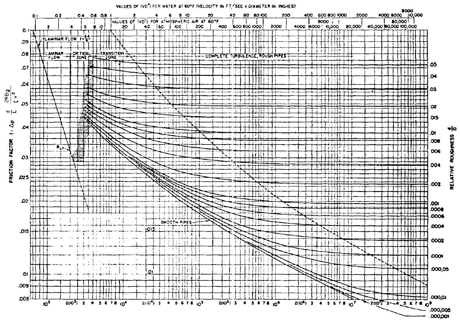 Figure 7-20.-Moody diagram.
of the design configuration. Sometimes the increased resistance of a specific flow passage can be accounted for by assigning to it a fictitious or equivalent length , of straight duct which is arrived at empirically. The sum of this equivalent length and the actual passage length, ( ), is then used in equation (7-7) for the calculation of turbulent flow. Figure 7-21 presents typical resistance characteristics of bends.
Because flow-control components such as valves and fittings disturb the flow pattern, they produce an additional pressure drop in a duct or line of tubing. The loss of pressure produced by a flow-control component consists of the pressure drop within the component itself, as well as the pressure drop in the upstream and downstream ducting or tubing in excess of that which would normally occur if there were no component in the line. With certain exceptions, the fluid
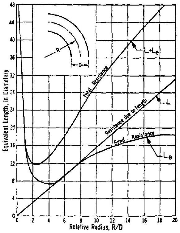 Figure 7-21.-Typical resistance characteristics of bends.
flows through rocket engine control components are usually treated as being turbulent. The true pressure drops chargeable to the components can only be evaluated accurately through actual flow tests.
Figure 7-22 shows a typical test setup for fluid-flow-control components. Pressure taps are located 4 diameters upstream and 10 diameters downstream of the component to be evaluated. This minimizes the flow disturbances at the pressure tapoff points caused by the components. The combination of pressure gages, U-tube manometer, and weighting tank produces quite accurate and repeatable test data. The net pressure drop caused by the component is obtained by subtracting from the measured that pressure drop which is caused by an uninterrupted straight pipe of the same size and length diameters, at the same flow conditions.
Because of the large number of fluid-flowcontrol components used in rocket engines and the great variety of service conditions, it is virtually impossible to obtain individual test data for every type and size of a component for the determination of pressure drop. It is desirable instead to extrapolate from test data which may be already available. This can be done by employing a component resistance coefficient when calculating pressure drop using the correlation
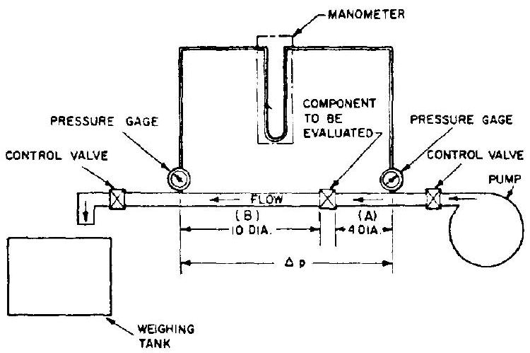 Figure 7-22.-Typical test setup for fluid-flow control components.
where
The coefficient is essentially constant for any given component over a large range of Reynolds numbers, providing the flow is turbulent. For a given type of component configuration, may vary with its size. A smaller size tends to have a higher value. In general, the higher the flow resistance of the component, the more nearly independent of size is the resistance coefficient . If a series of flow-control components of different sizes were geometrically similar (constant ratio in all the linear dimensions), the resistance coefficient would then depend upon the Reynolds number only and would not be influenced by component size. However, the design of a component is influenced by design standards, economy of material, structural strength, available space, etc. None of these considerations necessarily require geometric similarity of the various sizes of a given design. Average resistance coefficients for various fluid-flow-control components of liquid propellant rocket engines are presented in table 7-4.
For minimum pressure drop across a flowcontrol component, the following flow-passage design considerations should be observed: (1) Allow sufficient characteristic flow area for the component (2) Avoid abrupt changes of flow area (3) Avoid abrupt changes of wall contour, and sharp turns in the flow path (4) Minimize the length of the flow path within the component (5) Provide a smooth surface finish for the flow passages
TABLE 7-4.-Typical Resistance Coefficients for Various Fluid-Flow-Control Components of the Liquid Propellant Rocket Engines
| Component description | Resistance coefficient K |
|---|---|
| Butterfly-type valves (fig. 7-33): | |
| open | 0.31 |
| open | 41 |
| open | 77 |
| open | 1.98 |
| open | 5.68 |
| open | 15.45 |
| open | 44.7 |
| open | 124.2 |
| Ball-type valves (fig. 7-38): | |
| open | 0.81 |
| open | 1.58 |
| open | 3.6 |
| open | 18.2 |
| open | 63 |
| open | 362 |
| Poppet-type valves (fig. 7-40): Full open | 2.5-3.5 |
| Venturi-type valves (noncavitation) (fig. 7-41) | 0.8-1.5 |
| Gate-type valve (fig. 7-42): | |
| Full open | 0.18 |
| open | 1.20 |
| 1/2 open | 5.6 |
| 1/4 open | 24 |
| Poppet-type check valve (fig. 7-60) | 2 to 4 |
| Swing-gate-type check valve (fig. 7-61) | 1 to 2.5 |
| Standard tee | 1.8 |
| Standard elbow (909) | 90 |
| Medium sweep elbow | 75 |
| Long sweep elbow | 60 |
| elbow | 42 |
| Sudden enlargement: | |
| 0.92 | |
| 56 | |
| 50 | |
| Ordinary entrance | 50 |
| Sudden contraction: | |
| 0.42 | |
| 33 | |
| 19 |
The characteristics of fluids flowing through orifices will be further discussed in section 7.10.
Sample Calculation (7-2)
The following design data are given for the oxidizer pump discharge flexible duct and the main oxidizer valve (butterfly type) of the A-1 stage engine.
Liquid oxygen flow rate, Liquid oxygen density, Flexible duct inside diameter, in Flexible duct actual length, in Flexible duct equivalent length considering resistance due to flow passage contour deviation, Main oxidizer valve characteristic flow area percent of duct area
Estimate: (a) The pressure drop chargeable to the duct (b) The pressure drop chargeable to the valve
Solution
(a) Oxidizer flexible duct
The average flow velocity in the flexible duct
From table 6-3, the viscosity of liquid oxygen is ; thus (see eq. 7-6).
The Reynolds number of the flow in the duct
Use a surface roughness projection size of 0.00005 or a relative roughness
for the duct. From figure 7-20, friction factor, . Substitute the equivalent total length ( ) into equation (7-7). The pressure drop chargeable to the oxidizer flexible duct then is
(b) Main oxidizer valve
The characteristic velocity of the valve
From table , the resistance coefficient for butterfly valves . Substitute this into equation (7-9) to obtain the pressure drop chargeable to the main oxidizer valve:
Control Fluid Pressure Level
The working pressure level and the temperature of compressible fluid-flow-control system are important factors, since both govern the density of the fluid. Means of compensation for changes of pressure in a compressible fluid control system must always be provided. With an incompressible fluid, the pressure has relatively little influence on density.
The working pressure level of the fluid determines the selection of the structural design of the components as well as of the sealing methods, especially for dynamic seals. Special provisions are often made to meet the stringent requirements in high-pressure applications. For example, the cutoff events in a high-pressure turbopump-feed engine system may be sequenced so that turbine power is cut first; thus the main propellant valves are not required to shut off against the high main-stage discharge pressures.
Fluid-Flow Velocity
The requirements for smooth component-flowpassage contours are more critical with controls for compressible, or low-density, fluids such as hydrogen than for incompressible fluids, because their design flow velocities usually are much higher than those of the denser liquids. Also, in general the design trend for high-thrust, highpressure engine systems is toward smaller propellant duct and valve sizes, and consequently toward higher flow velocities (over 100 fps ).
An important consideration in the design of high velocity flow-control components is the high-impact loading imposed upon the control surfaces by the fluid stream. This is especially acute with the higher density liquids. To obtain reliable control performance characteristics with liquids at high velocities, the control components subject to impact loading must be designed to withstand the stresses involved. Also, they should be contoured so as to maintain small impingement angles with the fluid stream and to keep inpact forces to a minimum.
Fluid-Flow Temperature
Temperature is an important consideration for the design of fluid-flow controls. This is especially true if the controls are for fluids at temperatures in excess of, or far below, normal ambient.
In liquid propellant rocket engines, fluid-flow controls may have to handle hot gases at temperatures up to about . Example: the control of a turbine working fluid. Hot liquids need not be considered, since none of the liquid propellants have sufficiently low vapor pressures to permit handling at high temperatures. Ability to operate at elevated temperatures without any form of lubrication is a prime objective in the mechanical design of fluid-flow control. This can be accomplished by using bearings of either extremely hard, wear-resistant alloys, such as stellite and sintered carbides (high loading condition), or relatively soft materials such as graphite (low loading condition). Bearings are usually subject to compression loads only and are therefore not subject to failure if the materials used are of low ductility. For structural members not subject to wear or bearing loads, conventional high-temperature alloys such as stainless steels and other nickel-base alloys may be used. For static and dynamic seals, metal gaskets and bellows, carbon or graphite face seals, and labyrinth-type seals are suitable at high temperatures.
At the other end of the scale, liquid propellant rocket engine controls may see extremely low-temperature levels, such as in liquid hydrogen service ( ). Here, two principal conditions must be considered: (1) The physical characteristics of the fluids which at these low temperatures may affect control performance; and (2) the physical characteristics of the materials from which the control components are made and which may affect the operation and, thus, the performance characteristics of the control devices.
Many of the cryogenic fluids, i.e., liquefied gases, experience somewhat unpredictable phase changes (two-phase conditions) for relatively small temperature changes. No serious difficulties need to be expected, however, if the heattransfer rate from components in critical control areas is low enough to prevent vaporization of the liquid. This is particularly important in liquid hydrogen service, where insulation may pose difficult design problems. At any rate, except for viscosity changes, nearly all liquids exhibit more stable physical characteristics with large temperature variations, within the range between their freezing and boiling points, than do gases if the temperature range reaches to their liquefaction temperatures.
The construction materials for fluid-control components for low-temperature applications must be especially carefully selected. Practically every metal undergoes irregular phase changes at low temperatures which may seriously affect its physical properties. While the strength of metals generally increases with a decrease in temperature, further temperature decrease beyond certain limits may result in a decrease in strength. Many metals also become brittle at very low temperatures. Most of the aluminum alloys and the 300 -series stainless steels exhibit much better stability at temperatures in the cryogenic range than do others. Elastomers such as Teflon, Kel-F, and Mylar, when used for sealing purposes, exhibit satisfactory mechanical characteristics at extremely low temperatures. Teflon-coated surfaces additionally have good anti-icing characteristics. For further detail on materials, see chapter II.
Fluid-flow-control components for operation at cryogenic temperatures should be designed to be free of external icing effects. In addition to insulation, moisture-preventing purges should be provided internally in critical areas such as bearing interfaces. Also, actuators and/or bearings may require heating.
Rate of Response in Fluid-Flow Controls
Response rate is an important design consideration in any control system. Basically, the limiting factors governing response rate are (1) the speed with which signals can be transmitted, and (2) the mass/force ratio or its function, the inertia/force ratio of the main control organ.
In many fluid-control systems the controlled fluid is used to transmit the sensed signal. In others, part of the sensing link employs electrical or mechanical means. However, in most cases, part or all of the sensing loop utilizes an impulse generated by a pressure change. This impulse is transmitted at the speed of sound in the fluid. As a typical example, the velocity of sound in water is five times that in air; accordingly, a control signal would be transmitted five times faster in water.
The actuators for most fluid-flow-control mechanisms use pistons or diaphragms, powered by fluid pressure which, in turn, is regulated by some form of pilot valve. If suitable, the controlled fluid may be used as the actuating fluid. The response and flow capacity of the pilot valve, the effective area of actuator piston or diaphragm, and the actuating fluid pressure level influence directly the response rate of the control mechanism for given mass inertia and frictional or other resistances.
To satisfy certain operating conditions and to attain stable control it sometimes becomes necessary to introduce simple damping devices. In most control systems, stability is inversely proportional to sensitivity or response rate. Thus, the design of a fluid-flow-control system should reflect a realistic balance between sensitivity or response rate, control accuracy, and system stability.
Figure 7-23 illustrates the schematic of a typical piston-type actuator for fluid-flow-control devices. The piston when actuated moves against the spring in the direction of the arrow. The basic correlation between the response rate or acceleration of the piston, and other operational parameters, can be expressed by
where effective mass accelerated by the actuator piston, lb. It consists of piston mass, that of moving parts mechanically connected to the piston, and of the mass of all the fluid columns in the system
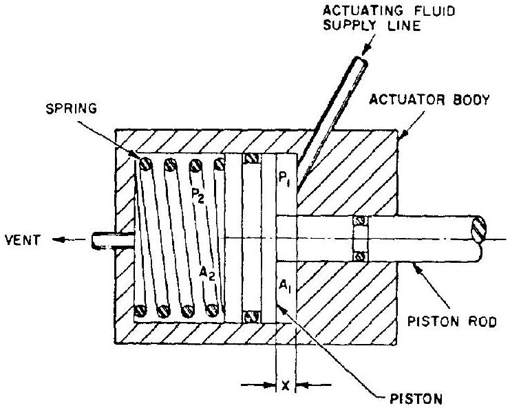 Figure 7-23.-Schematic of a typical piston-type actuator.
acceleration of the piston, area of the piston actuating side, in area of the piston vent side, in actuating pressure, psia. This is the pressure at the actuating fluid source, less the supply-line pressure drop which depends on the flow rate (a function of acceleration ) vent pressure, psia. This is the ambient pressure, plus the vent-line pressure drop which also depends on flow rate (again a function of acceleration ) resistance force of the control function, lb , which also may be a function of acceleration friction forces (seals, sliding surfaces, etc.), lb initial spring force, lb (at ) spring rate, in distance traveled by the piston from its initial position, in Since the relations between , and are not linear, equation (7-10) may become complex and require a high-speed computer for solution.