7.1 CONTROL METHODS
The foremost design requirements for any control system are accuracy, stability, and reliability. Two basic control methods are available: open-loop (no feedback) and closed-loop (feedback) control systems. Both have found wide application in liquid propellant rocket propulsion systems. Open-loop control is confined to those systems which are designed to operate at a fixed, steady-state level over a narrow range of environmental conditions. Most other applications require one of the many forms of closedloop control. For these, mathematical models can be constructed with which the functions and dynamics, such as gain factors and stability of a proposed system, can be analyzed.
The selection of the best-suited method then is an important first step in control systems design. It will be influenced by the required accuracy, the dynamic characteristics of the system being controlled, and by allowable timelags. Once the method is determined, the basic elements for the proposed system must be selected, such as type of components of the power supply or working fluid (electric, hydraulic, or pneumatic), and of the operating mechanism for the specific control, which all depend on the specific application. Ideally, the basic theories and past experience should permit design without experiment or development work. However, some development work with attendant redesign will always be required in the process of perfecting a new system.
Open-Loop Control
With this system, control is accomplished by preset control means, such as orifices, and onoff command devices. A typical example of open-loop control is an engine propellant flow system, calibrated to a fixed set of conditions. The propellant flows are controlled simply by opening and closing the propellant valves. Minor deviations from the design mixture ratio or propellant flow rates, such as from fabrication tolerances of engine components, are corrected beforehand by insertion of accurately sized orifices into the propellant flow lines to effect the desired pressure drops (also see ch. II). The extent of correction is determined from systems preflight calibration test data. Open-loop control has the advantage of simplicity. However, it is limited to a specific set of operating parameters, and is unable to compensate for variable conditions during operation.
Accurate sequencing of an open-loop control system such as is used for engine start and stop is usually accomplished with the aid of interlocks. Mechanical interlocks are preferred for their high reliability. For instance, the propellant valves of many small engines or gas generators are mechanically linked and are operated by a single actuator. Proper sequencing between fuel and oxidizer valves is achieved by adjusting the relative positions of the valve gates or poppets, with respect to the mechanical linkage. Interlock requirements can also be furnished by other means (electric, hydraulic, or pneumatic). In high-thrust engines, sequencing between main propellant valves and ignition system is often accomplished by the combination of various interlock designs. A typical example is the A-1 stage engine, for which the start and stop sequence and their interlocks were described in detail in chapter III.
Closed-Loop Control
Closed-loop control is also called automatic or feedback control. This system usually includes sensing means, computing means to detect errors, and control means to correct them. An accurately sensed feedback is compared with a fixed or variable reference by a computer, which then generates signals to correct for any deviations. The main system thus does not require precise calibration for a specific set of conditions. Unlike open-loop control, closed-loop control depends on sensing absence or presence of an error to maintain a desired condition or to bring about a correction. In general, the objective of closed-loop control is to minimize errors during operation and reduce system sensitivity to environmental changes and changes in component characteristics. It is applied to areas such as engine-thrust control and/or throttling, propellant mixture-ratio control, and thrust-vector control.
For rocket engine application, closed-loop control systems usually employ one or a combination of the following modes of operation:
- Simple "on" and "off" type.-(Example: pressure switch/valve combination for tank pressure control.)
- Proportional type.-Employs a continuous control signal which is proportional to the error. (Example: transducer output for chamber pressure control.)
- Derivative type.-Employs a continuous control signal which is a function of the error and its time derivative(s) (rate of change). This is principally used when systems stability is critical. (Example: thrust vector control system with phase lead.)
- Integral type.-Employs a continuous signal which is proportional to the cumulative integral of one or more errors. (Example: two flowmeter outputs for mixture-ratio control.)
Closed-loop or feedback control systems are essentially dynamic systems. Their design characteristics may be analyzed according to the basic laws of physics. Figure 7-1 shows a typical example. Its function is to maintain the controlled variable equal to the desired value , by manipulating the variable . Maintaining equal to is assumed to maintain the indirectly controlled quantity . In a typical turbopump fed engine control system, would be the combustion chamber pressure, maintained equal to a fixed reference pressure by means of a valve controlling the gas generator propellant flow then would be engine thrust, which is indirectly maintained at a desired value.
In this control system which consists of a sensor (chamber pressure transducer), a computer
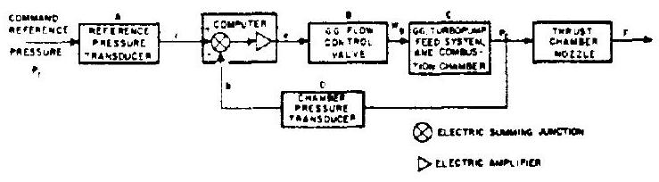 Figure 7-1.-Schematic of a typical closed-loop control system.
(electric summing junction and amplifier), and a controller (gas generator flow control valve), the command reference input is compared with the sensor feedback . The controller then manipulates in response to an error signal from the computer. Ideally, should be in linear proportion to and to , save for constants required to convert one physical quantity into the other. However, this ideal condition is difficult to attain because of the dynamic characteristics of the pressure transducers. These characteristics are influenced by physical properties such as mass inertia, fluid compressibility and viscosity, and frictional resistance. Instead of being directly proportional to , the two parameters are actually related through a differential equation which represents the dynamic behavior of the elements involved. The same is true for the feedback and the controlled variable . It is also applicable to other systems components. Hence, the analysis of a closed-loop control system usually involves the solution of sets of often complicated differential equations.
Refer again to figure , where is the controlled variable, the manipulated variable, the error signal, the feedback, the reference input, and the desired value. , and symbolically represent the dynamic relation between input and output of the respective components. The following terms representative of the differential equations for this closed-loop control system can be written:
The solution of these equations in combination with a systematic experimental program will suffice to analyze the dynamic performance of the system.
The continuous corrective action of a closedloop control system may promote dangerously unstable operation when control elements or components are employed having high gain and significant response lags. An unstable control system is one that is no longer effective in maintaining a variable at its desired value. Instead, large divergent oscillations may set in. The requirements for control accuracy and for stability are often difficult to combine. Higher accuracy requires high amplification; i.e., high gain. The high amplification results in overshoot during corrective action, thus promoting various degrees of system instability. However, through appropriate means of compensation, such as "anticipatory" phase leads (time derivatives), it is possible to obtain a high gain control system with satisfactory stability. Additional information on compensation will be presented in connection with thrust-vector control.