7.13 DESIGN OF LIQUID FLOW AND PRESSURE REGULATORS
Liquid flow and pressure regulators basically are variable-area-type, pressure-reducing valves. A liquid flow regulator maintains a constant rate of flow, or limits the maximum rate of a flow. A liquid pressure regulator, like a gas pressure regulator, maintains a constant fluid pressure at its outlet under variable flow conditions. Design considerations for liquid flow and pressure regulators are similar to those for gas regulators.
Design of Liquid Flow Regulators
Liquid flow control can be obtained with a venturi. The pressure at the throat is proportional to the velocity of the (incompressible) fluid and thus the flow rate. The pressure differential between throat and inlet can be used to control the position of a butterfly valve, and thus the flow rate, by means of a servocontrol circuit. A regulator of this type is shown schematically in figure 7-18.
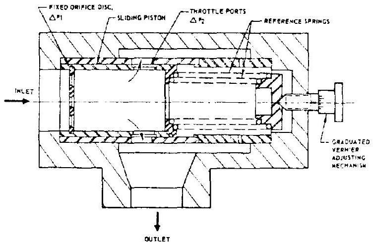
Figure 7-64 presents the principle of another type flow regulator which is frequently used in rocket engine systems, because of its simplicity. It consists of two restrictors, one of fixed and the other of variable area. This combination automatically maintains a constant pressure drop across the fixed restrictor, and thus a constant flow. The fixed restrictor consists of a disk containing a number of orifices and mounted in a piston. The variable restrictor is formed by variable throttle ports located around the piston periphery. The pressure differential across the fixed orifices causes the piston to move against the regulator reference springs. Piston throttle ports and reference spring rate are designed so
 Figure 7-64.-Schematic of a typical sliding-piston-type liquid flow regulator.
that a constant pressure drop is maintained across the orifice disk.
As the fluid inlet pressure increases, or the back pressure decreases, the flow rate tends to increase also. However, the attendant increase is pressure differential, i.e., pressure force on the piston, moves it against the reference springs, simultaneously increasing the flow restriction. A new equilibrium is achieved as the inlet pressure increase is absorbed by an increase in pressure drop across the piston throttle port.
The following design correlations are established for this flow regulator:
where
Adjustment of the regulated flow rate is made by adjusting the reference spring force, using a graduated vernier mechanism.
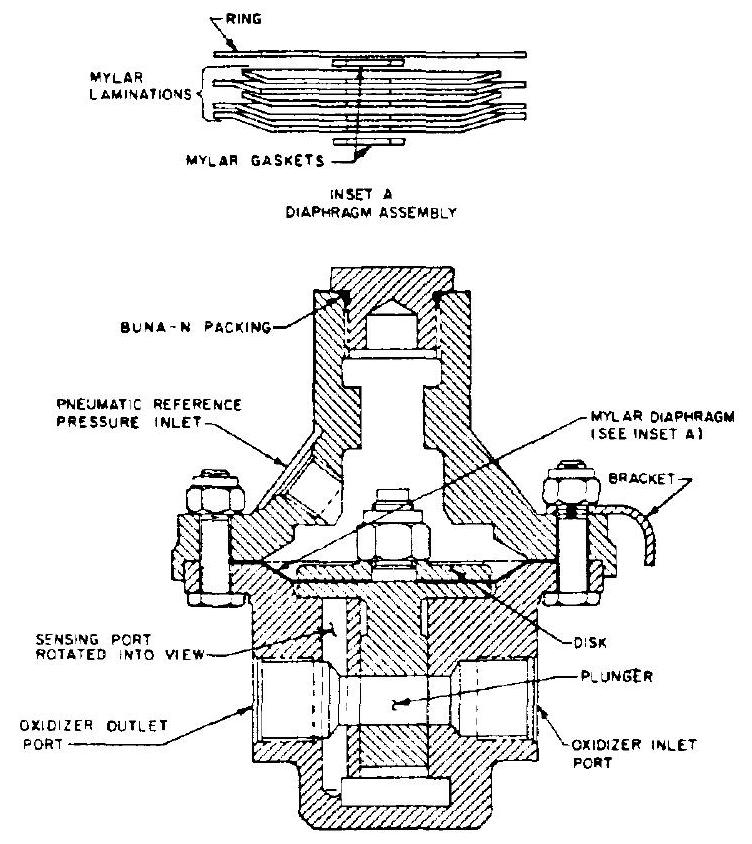
 Figure 7-65.-Typical liquid pressure regulator design for liquid oxygen service.
Design of Liquid Pressure Regulators
Figure 7-65 presents a liquid pressure regulator design frequently used in rocket engine systems. The actuator diaphragm of the regulator valve (plunger) can be loaded either by a pneumatic reference pressure (as shown), or by a reference spring.
Regulated outlet pressure is sensed directly. An increase in outlet pressure tends to reduce the flow area of the regulator valve until an equilibrium is reached between outlet pressure and reference pressure. The actuator diaphragm is made of Mylar laminations which are compatible with cryogenic propellants such as liquid oxygen.