7.12 DESIGN OF GAS PRESSURE REGULATORS
Basically, gas pressure regulators are variable-area-type pressure-reducing valves. Their prime function is to maintain constant pressure at their outlet, or in a downstream region, even though the pressure at their inlet may vary (decrease). Gas pressure regulators may be operated independently, or in conjunction with pressure relief devices, under either dynamic or static conditions. For example, the gas pressure regulator for the A-4 stage propulsion system (fig. 3-9) is designed to maintain a constant main oxidizer tank pressure of 165 psia , while the helium gas pressure at the regulator inlet varies from 4500 to 245 psia. Additional protection is provided by a tank relief valve, should the tank pressure continue to rise with the regulator completely closed, because of such effects as aerodynamic heating.
Elements of Gas Pressure Regulators
Most pressure regulators include two basic elements: the regulator controller and the regulator valve. The former controls the regulator valve opening, which in turn regulates the gas flow through the regulator.
A regulator controller essentially is a sensingcomputing unit which measures the difference between actual and desired pressure. Its output, called the error signal, can be directly applied mechanical force, or control pressure output to a servovalve. Figure presents the schematic of a typical gas pressure regulator controller. Here, the pressure being regulated is sensed externally by a bellows which is internally evacuated, or vented to atmosphere. The vacuum establishes an absolute pressure reference, while a vented bellows uses ambient pressure for reference ("gage pressure"). As the regulated pressure (the sensing pressure) changes, the bellows deflects against the calibrated internal spring load, simultaneously positioning a directly connected servovalve (fig. 7-57), which in turn regulates a control pressure output.
A regulator valve consists of the control valve and an actuator. If only limited accuracy is required, or very small capacities are involved, it suffices if the regulator controller develops the error signal directly as a mechanical force to position the regulator valve. Such a directly spring-loaded pressure regulator is represented schematically in figure 7-59(a).
Where greater accuracy is required, the regulator valve actuator is positioned by controlled pressure from a servovalve connected to the regulator controller.
Since the servovalve amplifies the regulated pressure errors, small errors in regulated pressure will cause large changes in its control pressure output. This control pressure can then be applied to control the regulator valve position in the following ways: (1) Control pressure is used as the loading pressure for a simple dome-loaded pressure regulator, as shown schematically
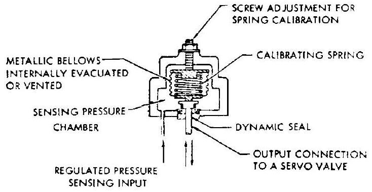 Figure 7-58.-Schematic of a typical gas pressure regulator controller.
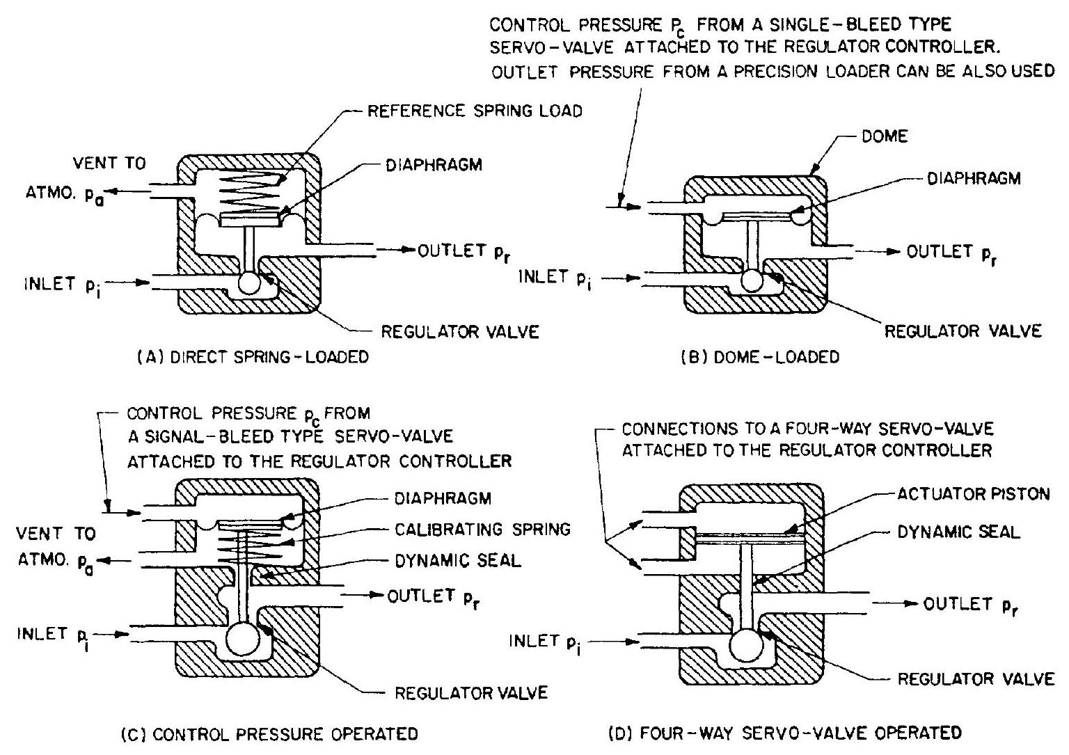 Figure 7-59.-Schematics of various gas pressure regulator designs.
in figure 7-59(b). A large-capacity, dome-loaded pressure regulator can also be loaded by a separate, small-capacity precision pressure regulator (precision loader). (2) Control pressure is used as the input to a mechanism that positions the regulator valve as a linear function of control pressure. In its simplest form, this mechanism consists of a spring and a diaphragm (fig. 7-59(c)). In some designs, a four-way servovalve (as in figs. and ) operates the double-acting piston-type actuator of the regulator controller to control the position of the regulator valve (fig. 7-59(d)). This design is known as an integratingtype pressure regulator.
When a single-bleed servovalve is used with the regulator controller, the supply pressure to the control servo circuit must be isolated from the inlet pressure to the main regulator valve, because of the steady-state error that would be introduced by the often extreme variation of . A simple, directly spring-loaded, low-capacity regulator similar to figure (a) is required to reduce to a reasonably constant supply pressure for the control servo circuit. This regulator is commonly known as the bleed regulator and can be a part of the main regulator controller.
Design Considerations for Gas Pressure Regulators
The following are basic considerations for the design of gas pressure regulators.
- The principal causes of error in a pressure regulator are- a. Variation in inlet pressure b. Variation in flow demand c. Variation in temperature d. Mechanical hysteresis and friction e. Creep of stress members f. Variation in effective length of members because of angular displacement g. Variation in vehicle acceleration h. Vibration i. The fact that pressures are not sensed at the point at which control of pressure is desired (influence of pressure drops caused by flow through downstream systems) The basic test of a good regulator design is whether these errors have been held within allowable tolerances, without mechanisms (including diaphragms and springs) of unreasonable complexity and size.
- Where feasible, proven concepts and control mechanisms of previous designs should be utilized. This is especially important for dynamic characteristics, stability and transient response, and for mechanical details such as poppets, seals, diaphragms, and springs.
- Balance of the regulator valve poppet should be provided to minimize the forces imparted to the valve by inlet pressure . This may be achieved by attaching a balance piston, similar to that of the poppet servovalves (fig. 7-57). However, this will require some type of dynamic seal, which are known trouble sources. In certain applications, therefore, an unbalanced valve may be preferred.
- In most cases, the regulator must lend itself to the alternate mode of operation as a shutoff valve, until a start pilot valve is opened.
- The various gas pressure regulator designs shown in figure 7-59 regulate pressure by admitting additional gas, as required to the regulated pressure region. If the flow demand on the regulator is reduced to zero (dead-end conditions), the regulator valve shuts off. However, the pressure in the regulated region may increase above the design point, even with the regulator valve closed, due to- a. A timelag in closing, following reduction of demand to zero b. Inevitable regulator valve leakage c. Thermodynamic effects, such as increase in temperature of the gas in the regulated pressure region, or from vaporization of a liquid. This condition is known as a lockup, and often poses problems. Lockup can be eliminated by incorporating a relief valve downstream of the regulator valve as part of the regulator assembly. In the A-4 stage propulsion system, individual
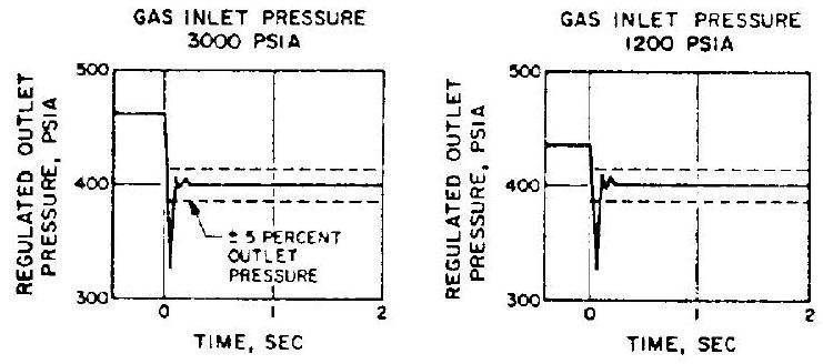 Figure 7-60.-Dynamic response characteristics of a typical pneumatic pressure regulator.
relief valves are provided for the main propellant tanks to prevent possible intermixing of propellant vapors. 6. Other design considerations for gas pressure regulators are- a. Type of regulated gas b. Gas inlet-pressure and temperature range c. Regulated gas outlet pressure level with respect to ambient or vacuum, its tolerance or accuracy of regulation, and range of adjustment d. Required maximum flow capacity e. Required response time and allowable overshoot f. Type of line connections g. Environmental conditions (temperature, vibration, humidity, etc.) Figure 7-60 presents the dynamic response characteristics of a typical pneumatic pressure regulator upon initiation of a demand. The regulator was set at a regulated outlet pressure of 400 psia . The gas used (helium) is discharged into a system of approximately 60 -cubic-inch volume.
Sizing of the Gas Pressure Regulator
The required flow area across the regulator valve when fully open, i.e., the characteristic flow area of a pressure regulator, may be calculated for required flow capacity and regulated outlet pressure, at minimum allowable gas inlet pressure.
The following correlation derived from equation (7-24) for gas flow orifices is applicable to gas pressure regulator design:
where characteristic area of the pressure regulator, in design weight flow rate of the pressure regulator, lb/sec gas constant, gas inlet temperature at minimum inlet pressure condition, compressibility factor, , a function of pressure ratio and specific heat ratio (fig. 7-53) flow coefficient, a function of design configuration. Design values range from 0.6 to 0.7 minimum allowable gas inlet pressure, psia required regulated outlet pressure, psia
Sample Calculation (7-11)
The following design data are given for the helium gas pressure regulator of the A-4 stage propulsion system:
Design weight flow rate, Minimum allowable gas inlet pressure, psia Gas inlet temperature at minimum inlet pressure condition, Required regulated outlet pressure, psia Regulator flow coefficient, Determine the characteristic area of the pressure regulator.
Solution
At minimum inlet pressure conditions, the pressure ratio across the regulator
From figure 7-53, the compressibility factor is 3.9 for helium. Substitute this and other data into equation (7-29). The characteristic area
Dome-Loaded Pressure Regulators
This regulator type (fig. 7-57(b)) is one of the most frequently used. The main actuator usually employs a metallic diaphragm for low friction. The dome pressure , which determines the force to the actuator diaphragm, and thus regulates valve position and outlet pressure, can be regulated either internally by a pressure controller, or externally by a low-capacity pressure regulator or loader. There are many variations of dome-loaded regulators. Design approaches may best be illustrated by typical examples.
Figure 7-61 presents the schematic of a typical dome-loaded gas pressure regulator which has an alternate mode of operation as a shutoff valve. The prime purpose of the regulator is to maintain a regulated outlet pressure at a preselected value called the set point. The regulator is composed of four elements: the start pilot valve, the bleed regulator, the sensingcontrol unit, and the main regulator valve. The combination of bleed regulator and sensingcontrol unit forms the function of main regulator controller.
The start pilot valve is a solenoid-actuated poppet valve which is normally held closed by a spring. In the closed position, it locks up the outlet pressure of the bleed regulator. The latter is a normally closed, directly spring-loadedtype, pressure-reducing valve and supplies an approximately constant preset pressure to the sensing-control unit. This pressure is greater than the main regulator outlet pressure . It is the sensing-control unit, then, which establishes the main regulator outlet pressure. It detects small deviations from the set point and magnifies the error signals by means of a single-bleed, flapper-nozzle servovalve linked to a sensor
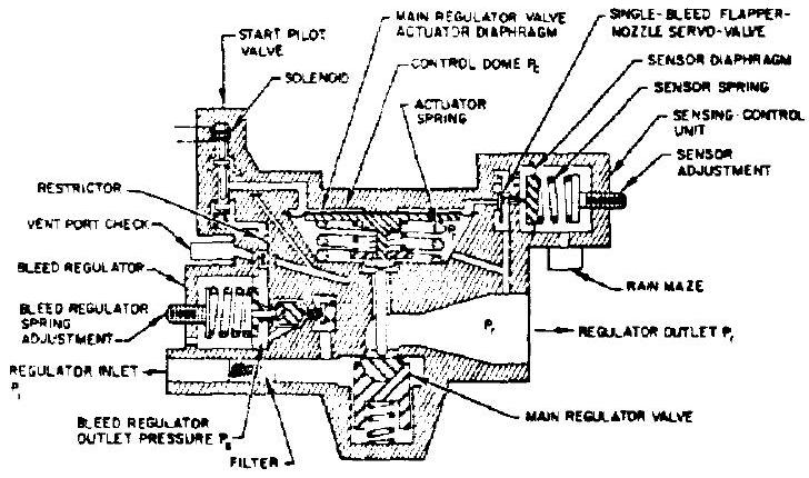 Figure 7-61.-Schematic of a typical dome-loaded, negative-gain-type gas regulator with an alternate mode of operation as a shutoff valve.
diaphragm by increasing or decreasing the control pressure which operates the actuator diaphragm of the main regulator valve. This valve is a normally closed, dome-loaded pressure reducing valve.
In operation, the following sequence of events occurs. Gas enters the regulator through a filter located at the regulator inlet port, but is prevented from entering the main regulator control pressure dome by the closed start pilot valve. Upon opening of the latter by energizing its solenoid, gas flows through the bleed regulator and is reduced to pressure , as determined by the preset reference spring force. The gas then flows through a fixed restrictor and passes into the control dome. This tends to open the main regulator valve against the actuator spring. Dome pressure is controlled by varying the flow area of the flapper-nozzle servovalve which bleeds the loading gas into the main regulator outlet manifold. When the sensed regulated outlet pressure and the sensor spring force are in equilibrium, the servovalve flapper is positioned a sufficient distance off the nozzle seat and maintains a steady-state control pressure . This pressure is always greater than , as determined by the main regulator valve actuator spring preload. Under these steady-state conditions, gas continues to flow from the bleed regulator through the servovalve at a rate determined by the restrictions and out to the outlet manifold. The regulator controller circuitry has what is called a negative gain. A sensed increase in pressure causes an amplified decrease in control pressure , with attendant decrease of the main regulator valve opening. Similarly, a decrease in causes an increase of valve opening.
The controller gain can be defined as
where = controller gain change in control pressure, psi change in sensed pressure, psi The principal design parameters of the gas pressure regulator shown in figure 7-61 are listed in table 7-6.
Figure 7-62 presents the design layout of a typical dome-loaded, zero-gain-type gas pressure regulator. The main regulator controller consists of a spring-loaded bleed regulator and a fixed-area bleed orifice, which gives a constant
Table 7-6.-Principal Design Parameters of a Typical Dome-Loaded, Negative-Gain-Type Gas Pressure Regulator (Fig. 7-61)
| Parameter | Design data |
|---|---|
| Regulated gas | Helium |
| Inlet gas pressure, . | 4500 psia nominal, 5800 psia maximum, 500 psia minimum |
| Inlet gas temperature, | to |
| Regulated outlet pressure, | |
| Flow demand | a. Maximum: at 500 psia inlet pressure and inlet temperature b. Minimum: zero |
| Modes of operation | a. Start pilot valve solenoid deenergized: regulator remains shut off. Outlet pressure |
| Controller bleed | a. None when start pilot valve solenoid deenergized |
| Main regulator valve. | Seating diameter, 0.205 in ; characteristic area, 0.0281 in |
| Main regulator valve actuator | Effective area, ; bias spring preload, 75.5 lb ; rate, |
| Start pilot valve | Seating diameter, 0.025 in ; characteristic area, |
| Bleed regulator valve | Seating diameter, 0.028 in ; characteristic area, |
| Bleed regulator sensor | Effective area, ; reference spring preload, 93.5 lb ; rate, |
| Bleed flow restrictor | Diameter, 0.0116 in ; area, |
| Main regulator controller sensor | Effective area, : reference spring preload, 126 lb ; rate, |
| Flapper-nozzle servovalve | Seating diameter, 0.043 in ( 2 holes); maximum stroke, 0.011 in ; maximum flow area, ; bias spring preload, 1.0 lb ; rate, |
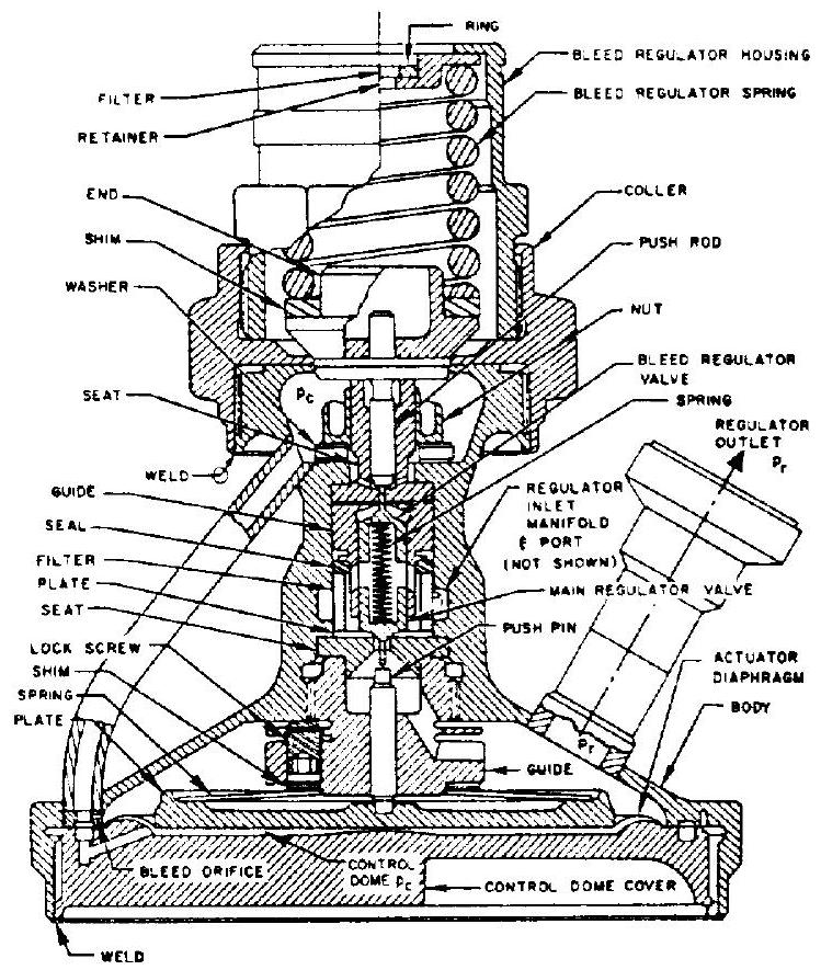 Figure 7-62.-Typical dome-loaded, zero-gaintype gas pressure regulator loaded by a bleed regulator.
bleed from the control dome to the regulator outlet. The control dome pressure is maintained at a constant level by the bleed regulator. This is known as a zero-gain-type control circuit. Here, too, control pressure is higher than the regulated outlet pressure by an amount determined by the main regulator valve actuator spring preload. The regulator shown is designed to maintain an outlet pressure of , at inlet pressures ranging from 5000 to 375 psig. The actuator diaphragms are made of a 0.0025 inch 17-7 PH high-strength stainless-steel sheet. 440 C stainless steel is used for all sliding members, such as regulator valve poppets and guides, to eliminate the surface galling problem. Regulator main body and housing are made of aluminumalloy forgings.
Integrating-Type Pressure Regulators
Figure 7-63 presents the design of a typical integrating-type gas pressure regulator, designed to regulate the propellant tank pressures of a pressurized gas propellant feed system such as the A-4 stage propulsion system. Main oxidizer
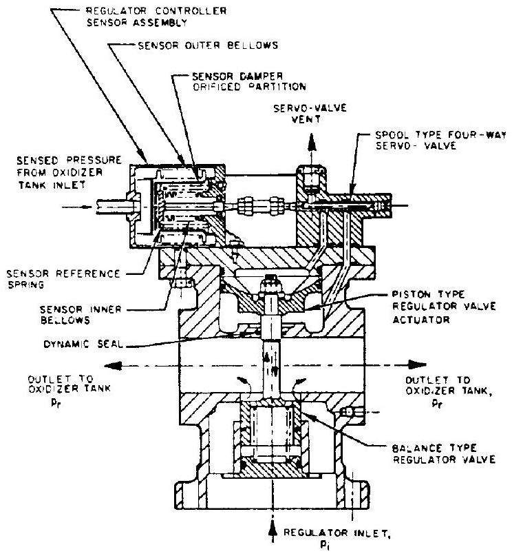 Figure 7-63.-Integrating-type, gas pressure regulator with spool-type, four-way servovalve.
tank pressure is to be sensed through a relatively short external line. Fuel tank pressure is maintained at 10 psi below the oxidizer tank pressure by different pressure settings of line check valves and tank relief valves. A spooltype, four-way servovalve, which is directly connected to the sensor of the regulator controller, controls the regulator valve actuator. Supply pressure of the servovalve is taken from the regulator outlet pressure ; i.e., . The sensor contains two bellows with an oil-filled damper in between. The damper consists of a partition having a properly sized orifice. The outer bellows, which is exposed to the propellant vapors, is hydroformed from thin 321 stainlesssteel tubing, because the pressure differential across it is small and because it contains fluid. The inner bellows must withstand a pressure differential equal to full tank pressure, since the interior of this bellows is vented directly to atmosphere. For this reason, the bellows is machined from 17-4 PH stainless-steel stock. This regulator is called an integrating type because a constant tank pressure error will produce a constant actuator piston velocity (neglecting extraneous forces). This, in turn, gives a constant regulator valve opening (or closing) velocity and a constantly increasing (or decreasing) gas flow rate. Tank pressure is then the integral of tank pressure error versus time. The integratingtype pressure regulator provides the constantly increasing regulator valve flow area required for decreasing supply pressures, with minimum error in tank pressure, but may be unstable if the gain of the servovalve-actuator combination is too high. A suitable gain value should be determined by computer studies of the regulator dynamic characteristics.