Except when used as inducers, application of axial-flow pumps in rocket engines is essentially limited to liquid hydrogen systems in a multistage configuration. Thus, the following discussions are applicable to axial-fiow hydrogen pumps only. Multistage axial-fow hydrogen pumps are applied in regions which are beyoad the capability of a single-stage centrifugal pump, since their construction is comparatively simple (fig. 6-4). As can be seen in figure 6-6, the fluid in an axial-flow pump flows from one stage to the next with a minimum of connecting passages.
The head rise of a typical single-stage centrifugal hydrogen pump is limited to about 65000 ft ( 2000 psi ). Beyond this point, a multistage
axial-flow pump is selected. For each stage of an axial-flow pump, head rises of 5000 to 9000 feet can be obtained.
The capacity of an axial-flow hydrogen pump is usually limited to about 5500 gpm as a minimum. This is due to the mininum practical height hV of the vanes (fig. 6-49). For heights below 0.5 inch, the tip clearance required for efficient performance becomes critical, causing manufacturing problems. A reduction in rotor diameter below certain values is not practical either, because of the high rpm required for proper blade speec.
Figure 6-50 presents typical operating regions of various liquid hydrogen pump types. These include centrifugal pumps of (NS)1=500per
Figure 6-49.-Eifect of vane height on the performance of an axial-flow pump.
Figure 6-50.-T'ypical operating regions of various pump types for liquid-hydrogen-fueled rocket engine applications.
stage (1 and 2 stages); centrifugal pumps of (Ns)1=1000 per stage (1 to 6 stages; not recommended for rocket engine use); and axial-flow pumps of (Ns)1=3000 per stage (1 to 12 stages). For any given operating region, there is usually a best-suited design configuration. However, overlapping regions occur which could be fulfilled by either a multistage axial-flow pump or by a single-stage centrifugal pump. 'The best solution then is dictated by other considerations, such as space envelope, mounting and ducting arrangement, and others. For instance, the requirements for the region above 5500 gpm , and head rises from 30000 to 65000 feet, could be met by either a single-stage centrifugal pump or a multistage axial-flow pump. The centrifugal pump also has its dimensional limitations. A value of less than 0.2 inch for the impeller discharge width, b2 (fig. 6-34), would complicate manufacture of shrouded impellers and make critical the tip clearance of an open-faced impeller. This establishes the lower capacity limit for centrifugal hydrogen pumps at about 250 gpm .
During operation of an axial flow pump, it is assumed that the meridional or axial component of the absolute flow velocity cm is constant throughout all stages of the impeller rotor and the stator. To satisfy the flow continuity equation, the cross-sectional areas of the various flow passages at right angles to cm must aiso remain constant. This assumption is reasonable, except for the effects of frictional drag at the casing wails and the vanes.
The main function of the impeller rotor of an axial-flow pump is to impart kinetic energy to the fluid by increasing the tangential component of the absolute flow velocity. This is accomplished by the action of airfoil-shaped rotor vanes (aigs. 6-51 and 6-52). It is convenient to describe the vanes on several developed cylindrical sections. Three sections are of particular interest: at the impeller tip diameter dt, at the impeller hub dh, and at its mean effective diameter dm (inches). The mean effective diameter is defined by
dm2=2dt2+dh2=2dt2(1+rd2)(6-79)
where rd= impeller hub ratio or dh/dt.
For simplicity, vane characteristics and flow conditions are discussed here only with respect to the mean effective diameter dm. The vanes are equally spaced at a circumferential distance Pt
Pr=zrπdm(6-80)
where
Pr= pitch or rotor vane spacing at the mean effective diameter din, in zr= number of rotor vanes
The ratio of the rotor vane chord length Cr to the pitch Pr is called rotor vane solidity Sr
Sr=Pr′Cr(6-81)
where Sr= rotor vane solidity at the mean effective diameter dm.
The chord to pitch ratio generally increases from rotor tip diameter dt to hub diameter dh for structural reasons. The profile of the vane can be represented by the vane mean line (fig. 6-52) which determines most of the important hydraulic properties of the vane. The thickness of the vane varies along the mean line for better performance and for structural strength. To impart effectively the driving action to the fluid, the angle of the vane mean line, or rotor vane angle,
Figure 6-51.-Inducer, inducer stator, impeller rotor, and impeller stator of an axial-flow pump.
Figure 6-52.-Vane elements and flow velocity diagrams of axial-flow pumps.
is gradually increased from β2 to β3. The difference between the two, β3−β2, is a measure of the vane curvature along any particular vane section. Generally, in axial-flow pump designs, all vane mean lines can be approximated by a circular arc. The following correlations can be established:
where
βc= chord angle of the rotor vane, deg
β2= vane angle at the rotor inlet, deg
β3= vane angle at the rotor outlet, deg
Cr= chord length of the rotor vane, in
RI= radius of the rotor vane curvature, in
LI= axial length of the rotor vane, in
(All parameters refer to the mean effective diameter, dm )
An angle of attack or incidence angle " i " between rotor inlet vane angle β2 and the direction of the relative velocity of the flow entering the rotor, β2′, is allowed for more effective driving of the fluid. Also, an angle "ii" is allowed for circulatory flow between the rotor outlet vane angle β3 and the direction of the relative velocity of the flow leaving the rotor, β3′. For the design of impeller rotors, velocity diagrams of the flows at the inlet and outlet of rotor vanes can be constructed (fig. 6-52) with the following correlations:
i =angle of attack, deg ii =angle allowed for circulatory flow at the outlet, deg β2′,β3′= relative flow angles at the rotor inlet and outlet, deg a2′,a3′= absolute flow angles at the rotor inlet and outlet, deg cm= meridional or axial component of the absolute flow velocities, ft/sec um= rotor peripheral velocity at mean effective diameter dm,ft/secc2′,c3′= design absolute flow velocities at the rotor inlet and outlet, ft/seccu2′,cu3′= tangential components of the design absolute rotor inlet and outlet flow velocities, ft/sec v2′,v3′= design relative flow velocities at the rotor inlet and outlet, ft/sec Qimp = required impeller flow rate at the rated design point, gpm Q= rated design pump flow rate, gpm Qe= impeller leakage loss rate, gpm (2 to 10 percent of Q ) ϵ= contraction factor of vane passage (0.85 to 0.95) ΔHimp = required developed head per impeller stage, ft (ΔH)1= rated design developed head per axial-flow pump stage, ft He= hydraulic head losses per stage of impeller stator, ft (ψ)1 = head coefficient per axial flow pump stage
(All applicable parameters refer to the mean effective diameter, dm )
At various cylindrical sections between vane tip diameter dt and hub diameter dh, the following correlations between vane angles and flow velocities are established:
The purpose of the stator of an axial-flow pump is to convert a major portion of the tangential component of the absolute flow velocity leaving the rotor into static pressure. This is accomplished by "straightening" the flow as it leaves the rotor. The stator vane curvature is designed so that the fluid enters the vanes with minimum loss, and leaves the stator with a reduced tangential component of the absolute flow velocity. The cross-sectional areas of the stator flow passages normal to the axial direction are equal to those of the rotor. Thus, the axial component of the absolute flow velocity is maintained. The dimensions dt and dh of the stator can be treated as equal to the tip and hub diameters of the rotor. The chord-pitch ratio of the stator vanes generally increases from hub diameter dh to tip diameter dt. The axial length Ls of the stator vane at the mean effective diameter is usually made equal to that of the rotor, Lr.
Referring to figure 6-52, the velocity diagrams at the stator inlet and outlet are constructed with the assumption that the absolute flow velocities and angles at stator inlets and outlets are equal to the corresponding ones at the rotor outlets and inlets. This facilitates the design of multistage axial-flow pumps using uniform rotor and stator stages.
To deflect the fluid effectively, the stator inlet vane angles a3 should be greater by a few degrees than the inlet absolute flow angles α3′; i.e., an angle of attack " i " should be allowed. Also, an angle "ii" should be allowed between outlet vane angle a4 and outlet absolute flow angle a4′ for the circulatory flow (boundary condition). The following correlations can be established for the vane and flow velocity diagrams of the stator (fig. 6-52):
a3,a4= vane angles at stator inlet and outlet, deg
RS= radius of the stator vane curvature, in
LS= axial length of the stator vane, in
i= angle of attack, deg
ii == angle allowed for circulatory flow at the outlet, deg
a3′,a4′= absolute flow angles at stator inlet and outlet, deg
cm= axial component of the absolute flow velocities, ft/sec
c3′,c4′= design absolute flow velocities of stator inlet and outlet, ft/seccu3′,cu4′= tangential components of the design absolute velocities at stator inlet and outlet, ft/seca3t,a3h,a3x= stator inlet vane angles at tip, hub and any intermediate diameter, deg
a4t,a4h,a4x= stator outlet vane angles at tip, hub and any intermediate diameter, deg
(All parameters refer to the mean effective diameter dm, unless specified differently.)
A number of design factors directly affect the performance and characteristics of an axial flow pump. Evaluation of test information, on the basis of specific speed per stage (NS)1, shows definitely the following correlations:
Impeller hub ratio, rd.-The ratio of impeller hub diameter dh to tip diameter dt (fig. 6-51) has a direct bearing on the specific speed per stage (Ns)1. Higher specific speed pumps have smaller hubs or hub ratios which results in greater free flow area, and thus greater capacity, but lower head ( H/Q characteristics). On the other hand, a higher hub ratio tends to yield a higher head coefficient per stage (ψ)1. Typical values of rd in rocket engine hydrogen pump designs range from 0.76 to 0.86 . Typical design values for (NS)1 and (ψ)1 range from 3000 to 5000 , and from 0.25 to 0.35 , respectively.
Vane solidities SI,SS. -The vane solidities or chord-spacing ratios of the rotor and stator are important design parameters. They are selected on the basis of previous experience.
A higher pump specific speed is linked with lower solidity. Typical design values for vane solidities for the rotor and stator at the mean effective diameter dm range from 1 to 1.3, and 1.5 to 1.8 , respectively.
3. Number of vanes zr,zs.-A lower pump specific speed generally results in a larger number of vanes. Design values of zr range from 14 to 20 . Design values of zs vary between 35 and 45. Their number should have no common factor with zr.
4. Vane curvature and vane setting.-Experiments indicate that the head developed by an impeller rotor is essentially determined by the vane curvature; i.e., β3−β2. Changes in vane settings, i.e., outlet vane angle β3 and inlet vane angle β2, by the same amount ( β3−β2 = const) will not affect head rise and efficiency materially.
The design procedure for the impeller rotors and stators of a multistage axial-flow pump is essentially the same as that for a single-stage centrifugal pump, except for the determination of the number of pump stages. Design parameters and coefficients established experimentally with earlier successful designs should be utilized to the fullest. Special development tests are still required to verify the characteristics of the new design. The design procedure includes the following steps:
To meet a given set of engine system requirements such as rated design pump developed head H, flow rate Q, and rated pump (NPSH) c, the pump rototing speed N is determined first through selection of a suitable inducer of agiven suction specific speed (Nss)ind .
With N established, selection of impeller rotor and stator of a given specific speed per stage (Ns)1, combined with the determination of the number of pump stages, can now proceed with the aid of the following correlations.
(NS)1=N= specific speed per axial-flow pump stage rated design pump rotating speed, rpm
Q = rated design pump flow rate, gpm
(ΔH)1= rated design pump developed head per axial-flow pump stage, ft
ΔH = rated design pump overall developed head, ft
ΔHind = inducer rated head rise, ft
Hee = hydraulic head loss at the inducer stator, ft
r = number of axial-flow pump stages
3. For the specific speed per stage (Ns)1 thus obtained, various design factors and coefficients such as impeller hub ratio rd, vane solidities Sr and SS, number of vanes zr and zS, head coefficient per stage (ψ)1, etc., are selected based on past designs with comparable (NS)1 values.
4. The required impeller rotor and stator diameters, velocity diagrams and vane profiles can now be derived from equations (6-79) through (6-105).
Impeller rotor and stator vanes are generally machined from forgings (fig. 6-51 and 6-53) using aluminum alloys or nickel-base alloys such as K-Monel. In view of the relatively low head produced by an individual axial-flow impeller stage, reduction of skin friction and flow turbulence losses are more important than with centrifugal pumps. A high degree of vane streamlining and polishing is required for high efficiency.
The axial distance da between impeller rotor vanes and stator vanes (fig. 6-51) has some bearing on performance. Typical design values of da range from 0.02 to 0.05dt, where dt= the
Figure 6-53.-Inducer, impeller rotor, and turbine rotor assembly of a typical multi-stage axialflow pump.
impeller tip diameter. Design values for tip clearances. c, between rotor and stator (fig. 6−49 ) range from 0.005 to 0.010 inch.
The vane thickness along the mean line is mainly determined by structural considerations, since experiments indicate that there is very little effect on performance from variation of vane thickness. The problems with stressing pump rotor vanes are similar to those with turbine blades. The methods given in section 6-5 for turbines can be applied here also. Vane stresses incluae centrifugal stresses, bending stresses due to lift and drag loadings on the vanes, and vibrational stresses.
Design of Cavitating Inducers for Axial-Flow Pumps
The design procedures and parameters for cavitating inducers in axial-flow pumps are essentially the same as those for a centrifugal pump (fig. 6-51). Usually, the inducer has a cylindrical tip contour and the same tip diameter dt as the impeller. The contour of the inducer hub is highly tapered ficm a relatively small diameter at the inlet to a diameter close to that of the impeller at the outlet.
An inducer stator, which also saives as the front bearing support, is positioned behind the inducer rotor. It is designed to convert into pressure, a portion of the tangential component of the absolute flow velocity leaving the inducer, and to discharge the fluid at an absolute flow velocity and angle equal to that at the outlet of an impeller stator ( c2′=cu′ ). The inducer stator has the same dh and dt as the impeller, and thus the same effective passage cross-sectional area normal to the axial velocity componant cm. The inlet and outlet velocity diagrams for the inducer stator are shown in figure 6-52. The following correlations can be established for the design of an inducer stator:
Pis = pitch or inducer stator vane spac- ing, in zis = number of inducer stator vanes Sis = inducer stator vane solidity Cis = inducer stator vane chord length, in aic= chord angle of the inducer stator vane, deg a1,a2= vane angles at inducer stator inlet and outlet, deg. Ris = radius of the inducer stator vane curvature, in Lis = axial length of the inducer stator vane, in i = angle of attack, deg ii = angle allowed for circulatory flow at the outlet, deg a1′,a2′= absolute flow angles at inducer stator inlet and outlet, deg cm= axial component of the absolute flow velocity, ft/secc1′,c2′= design absolute flow velocities at inducer stator inlet and outlet, ft/sec c1u′,c2u′= tangential components of the design absolute velocities at inducer stator inlet and outlet, ft/sec a1t,a1h= inducer stator inlet vane angles at tip and hub diameters, deg a2t,a2h= inducer stator outlet vane angles at tip and hub diameters, deg a1X,a2X= vane angles at any diameter dX (All parameters refer to the mean effective diam- eter dm, unless specified differently.)
Inducer stator vane solidity design values range from 1.5 to 1.8 ; the number of vanes zis , ranges from 15 to 20 . The number zis should have no common factor with the number of impeller rotor vanes, zr.
As shown in figures 6-6 and 6-54, the casing of an axial-flow pump consists of a cylindrical section which houses the inducer stage and the impeller stages. It also includes a volute section with radial guide vanes which is located behind the last impeller rotor stage. In addition to converting the tangential flow velocity component into pressure, the volute section also serves to reduce the axial velocity component by gradually increasing the flow area toward the volute discharge.
The radial guide vanes of the volute section are designed such that the fluid enters them with minimum losses and that it leaves them in a radial plane, analogous to a centrifugal pump (fig. 6-46). The number of radial guide vanes usually ranges from 17 to 23 . They should have no common factor with the number of impeller rotor vanes. Vane angle αV can be determined by constructing the flow velocity diagram for that section.
The calculations of the required areas at the various sections of an axial flow pump volute are essentially identical to those for a centrifugal pump (eqs. 6-69 and 6-70). For liquid hydrogen, design values for volute flow velocities range from 100 to 150ft/sec. The section of the volute is generally circular in shape to accommodate the high pressures. First-class thermal insulation should be applied to the pump outside surfaces. This will prevent excessive hydrogen boiloff.
Balancing the Axial Thrust of Multistage Axial-Flow Pumps
Balancing of the combined axial thrust of a multistage axial-flow pump is an important function, in view of the high pressures involved. Special balancing devices, such as automatic balance pistons, are frequently used. The balance piston is secured to the rotor assembly, as
shown in figure 6-54. It consists of a disk having small clearances with a pair of seal rubs. located on either side of the disk. A forward movement (toward the inlet) of the rotor assembly, and thus the balance piston, reduces the clearance at the front seal rub, simultaneously increasing it at the rear seal rub. As a result, the pressure in the control chamber between front and rear seal rubs is reduced. This effect counteracts the forward hydraulic axial thrust of the rotor assembly and restrains its forward motion. Similarly, a rearward movement (reverse thrust) of the rotor assembly is counteracted by a pressure increase in the control chambers. The volume to the rear of the control chamber, through cavities in the rotor, communicates with the lowpressure region of the pump inlet. The variation in forward axial thrust can be expressed as
ΔTa=Δpc4π(df2−dr2)(6-117)
where
ΔTa=Δpc=df=dr= variation of the forward hydraulic axial variation of the fluid pressure in the con- trol chamber, psi diameter of the front seal rub, in diameter of the rear seal rub, in
The following design data, based on engine system requirements and on experimental model test results, are given for the alternative A-2 stage engine fuel (liquid hydrogen) pump, based on an axial-flow, multistage configuration (similar to figs. 6-51 and 6-54).
Figure 6-54.-Axial-flow pump volute casing and balance piston arrangement.
Rated design pump developed head, ΔH
=44800ft
Rated design pump flow rate, Q=6080gpm
Rated design pump ( NPSH )c=135ft
Inducer general configuration = cylindrical tip contour; tapered hub contour
Inducer suction specific speed, ( Nss ) ind =53400
Inducer inlet flow coefficient, ϕi=0.09 max
Inducer head coefficient, ψind =0.307
Inducer leakage loss rate, Qee=0.03Q
Inducer stator head loss, Hee=0.08ΔHind
Inducer stator vane solidity, Sis=1.53
Number of inducer stator vanes, zis=17
Specific speed per axial-flow pump stage, (NS)1=3200
Head coefficient per axial-flow pump stage, (ψ)1=0.304
Impeller hub ratio, rd=0.857
Impeller leakage loss rate, Qe=0.06Q
Head loss per stage of the impeller stator, He=0.08(ΔH)1
Impeller rotor vane solidity SΓ at the mean effective diameter =1.05
Number of impeller rotor vanes, zI=16
Impeller stator vane solidity Ss at the mean effective diameter = 1.61
Stator and rotor vane passage contraction factor, ϵ=0.88
Angle of attack at the vane inlet, i=4∘
Angle allowed for circulatory flow at the vane outlet, ii=5∘
Calculate and design basic pump dimensions and vane detail of: (a) inducer stator, and (b) impeller rotor and stator.
We use a hub diameter d0h=2.9 inches at the inducer inlet. Considering that we are using a cylindrical tip contour, the absolute inlet velocity and its meridional component of the inducer flow result from equation (6-59) as:
Check for inducer inlet flow coefficient:
ϕind =utcmo =82664.8=0.0784(<0.09max. specified )
Use identical values cm for the meridional component of the absolute flow velocities through the inducer outlet, the stators and the rotors. From equation (6-86)
From equation (6-60), the required hub diameter at the inducer outlet
d1h=dt2−3.12×4π×cmQind
=49−3.12×4π×2306450=6.13in
The mean effective diameter at the inducer outlet
d1=2dt2+d1h2=249+37.58=6.57in
The peripheral speed at d1
u1=720Nπd1=72027000×π×6.57=774ft/sec
From equation (6-66), the tangential component of the inducer design absolute outlet flow velocity,
cu1′=ΔHind u1g=7746500×32.2=270ft/sec
The inducer design absolute outlet flow velocity
c1′=cu1′2+cm2=72900+52900=354.7ft/sec
The inducer design absolute outlet flow angle
tanα1′=cu1′cm=270230=0.852;a1′=40∘26′
We use an inducer stator with a meridional flow area equal to that of the impeller rotors and stators (i.e., dt=7in,dh=6in,dm=6.52in, and ϵ=0.88 ). We also assume that the absolute flow conditions at the inducer stator inlet are identical to those at the inducer outlet. From equation (6-112), the stator inlet vane angle at dm
a1=a1′+i=40∘26′+4∘=44∘26′
For a design absolute flow angle at the stator outlet, a2′ of 65∘, equation (6-113) yields a vane angle at the stator outlet
a2=a2′+ii=65∘+5∘=70∘
The tangential component of the stator absolute outlet flow velocity
cu2′=tana2′cm=tan65∘230=2.145230=107.2ft/sec
Assume that the design absolute flow conditions at the impeller rotor inlets and at the impeller stator outlets are identical to those at the inducer stator outlet. Thus
The design relative flow angle at the impeller rotor inlets
tanβ2′=um−cu2cm=768−107.2230=0.344;β2′=19∘
The relative flow velocity at the impeller rotor inlets
From equation (6-85), the rotor outlet vane angle at dm
β3=β3′+ii=29∘26′+5∘=34∘26′
From equation (6-80), the rotor vane pitch
Pr=zrπdm=16π×6.52=1.281in
From equation (6-81), the chord length of the rotor vanes at dm
Cr=SrPr=1.05×1.281=1.346in
From equation (6-82), the chord angle of the rotor vanes at dm
βc=2β2+β3=223∘+34∘26′=28∘43′
From equation (6-83), the axial length of the rotor vanes
Lr=Crsinβc=1.346×sin28∘43′=0.645in
The radius of the rotor vane curvature at dm
Rr=2sin2β3−β2Cr=2sin5∘33′1.346=6.95in
Assume that the design absolute flow conditions at the impeller stator inlet are identical to those at the impeller rotor outlet. From equation (6-101), the impeller stator inlet vane angle at dm
a3=a3′+i=32∘40′+4∘=36∘40′
From equation (6-102), the impeller stator outlet vane angle at dm
a4=a4′+ii=65∘+5∘=70∘
The axial length of the stator vanes at dm is equal to that of the rotor vanes; thus
LS=Lr=0.645in
From equation (6-99), the chord angle of the stator vanes at dm
ac=2a3+a4=236∘40′+70∘=53∘20′
From equation (6-100), the chord length of the stator vanes at dm
Cs=sinacLs=sin(53∘20′)0.645=0.805in
The radius of the stator vane curvatures at dm
Rs=2sin(2a4−a3)Cs=2sin(16∘40′)0.805=1.41in
From equation (6-98), the stator vane pitch at dm
Ps=SsCs=1.610.805=0.5in
From equation (6-97), the number of the stator vanes
zs=Psπdm=0.5π×6.52=41
A-2 Stage Engine Fuel Pump Impeller Rotor and Stator Design Summary
(Unless otherwise specified, data are all at the mean effective diameter dm.)
Rotor inlet flow velocity diagram (fig. 6-52), a21=65∘;β21=19∘;um=768ft/sec;v21=699.6ft/sec;c2′=253.8ft/sec;cu2′=107.2cm=230ft/sec
Rotor outlet flow velocity diagram (fig. 6-52), a3′=32∘40′;β3′=29∘26′;um=768;v3′=468.7ft/sec;c3′=426.9ft/sec;cu3′=359.6ft/sec;cm=230ft/sec
Stator inlet flow velocity diagram (fig. 6-52), a3′=32∘40′;c3′=426.9ft/sec
Stator outlet flow velocity diagram (fig. 6-52), a4′=65∘;c4′=253.8ft/sec;cu4′=107.2ft/sec;cm=230ft/sec
Nominal rotor and stator tip diameter, dℓ=7in Nominal rotor and stator hub diameter, dh=6 in Nominal rotor and stator vane height, hv=0.5 in
Nominal mean rotor and stator effective diameter, dm=6.52in
Rotor vane elements (fig. 6-52), β2=23∘;
β3=34∘26′;βc=28∘43′;Sr=1.05;zr=16;Pr=1.281in;Cr=1.346in;Lr=0.645in;Rr=6.95in
Stator vane elements (fig. 6-52), a3=36∘40′; a4=70∘;aC=53∘20′;SS=1.61;zS=41;PS=0.5;CS=0.805in;LS=0.645in; RS=1.41in
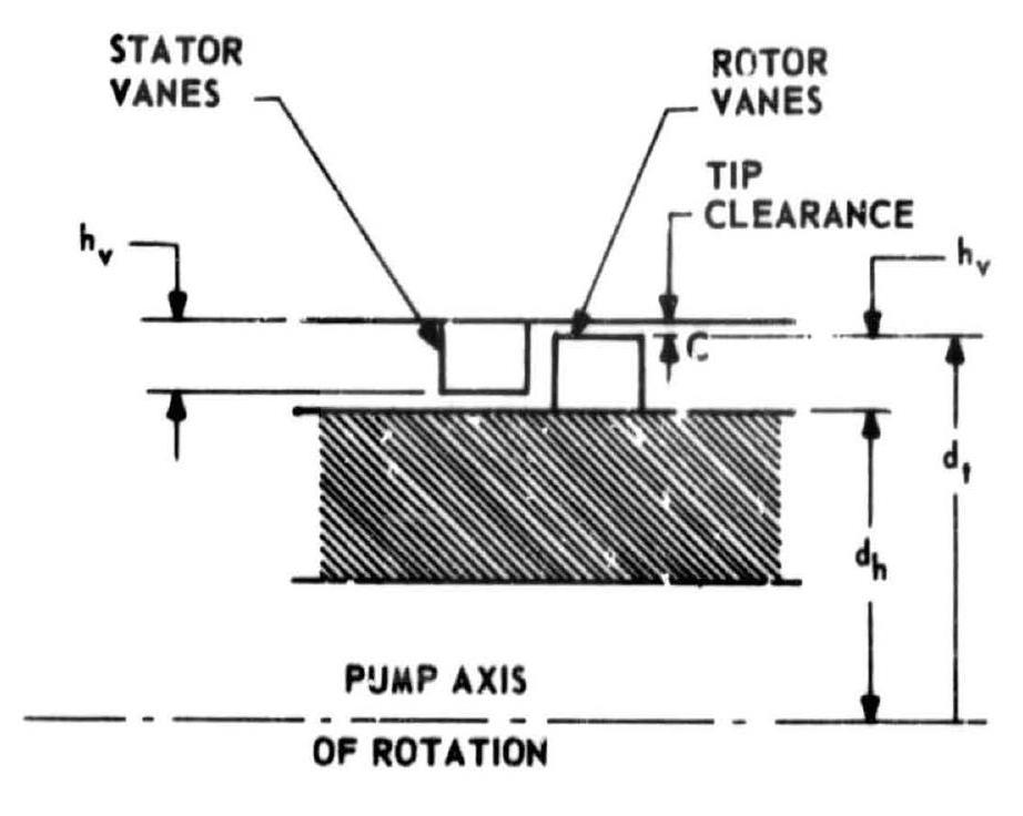
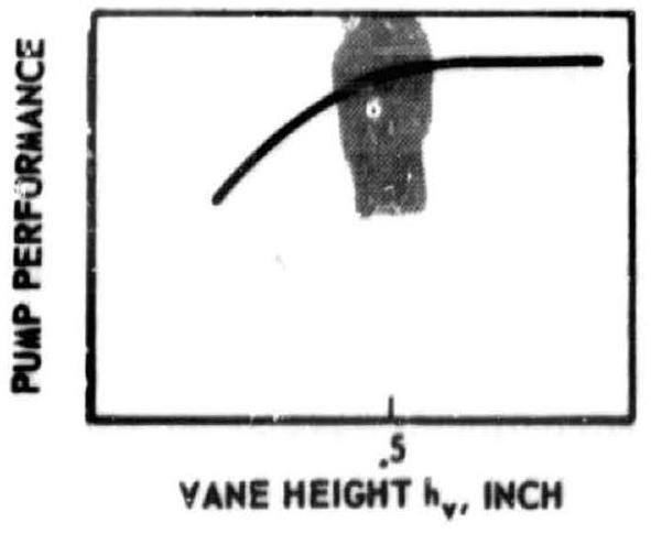 Figure 6-49.-Eifect of vane height on the performance of an axial-flow pump.
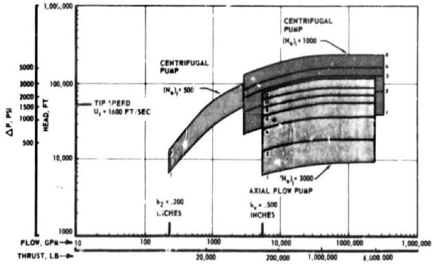 Figure 6-50.-T'ypical operating regions of various pump types for liquid-hydrogen-fueled rocket engine applications.
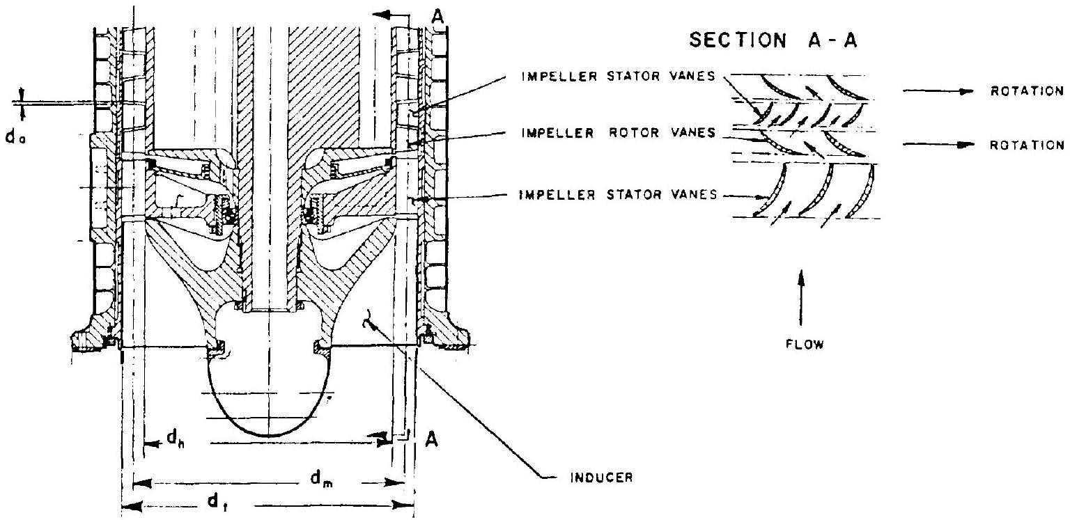 Figure 6-51.-Inducer, inducer stator, impeller rotor, and impeller stator of an axial-flow pump.
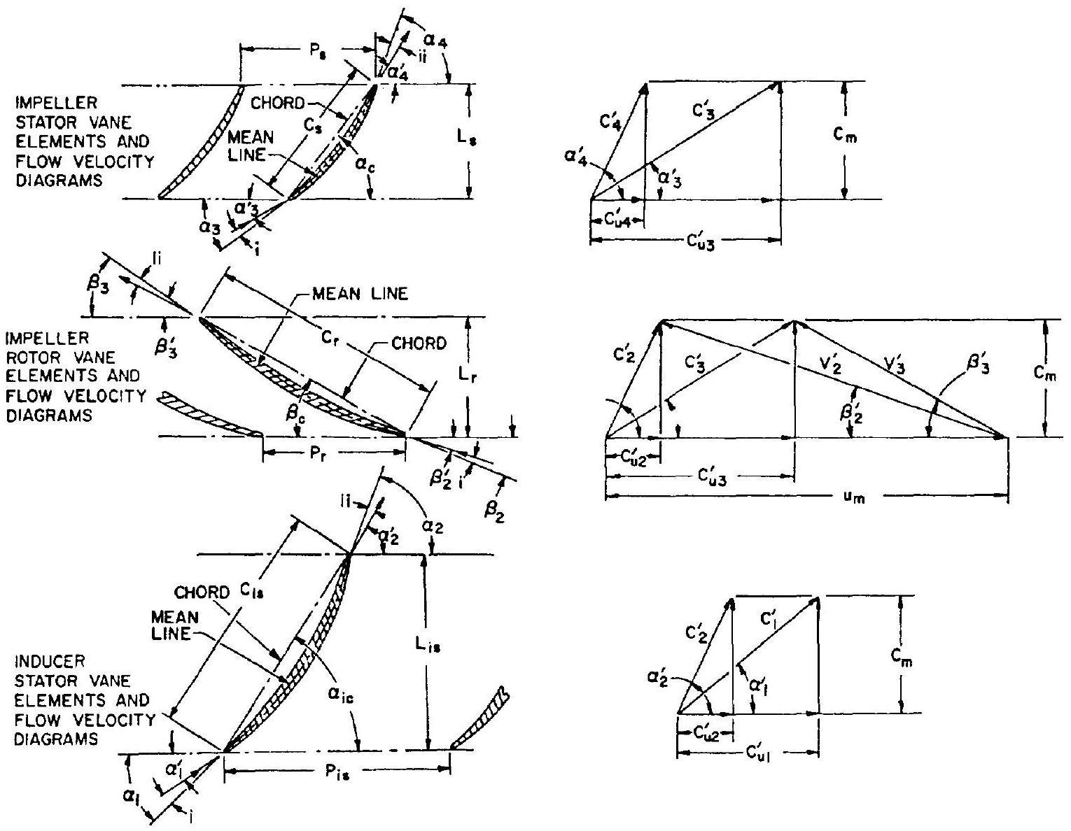 Figure 6-52.-Vane elements and flow velocity diagrams of axial-flow pumps.
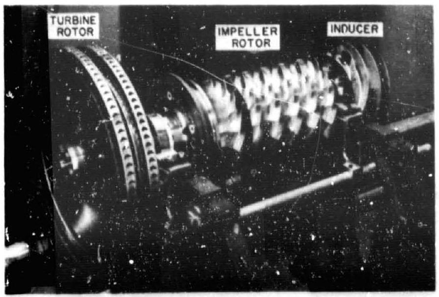 Figure 6-53.-Inducer, impeller rotor, and turbine rotor assembly of a typical multi-stage axialflow pump.
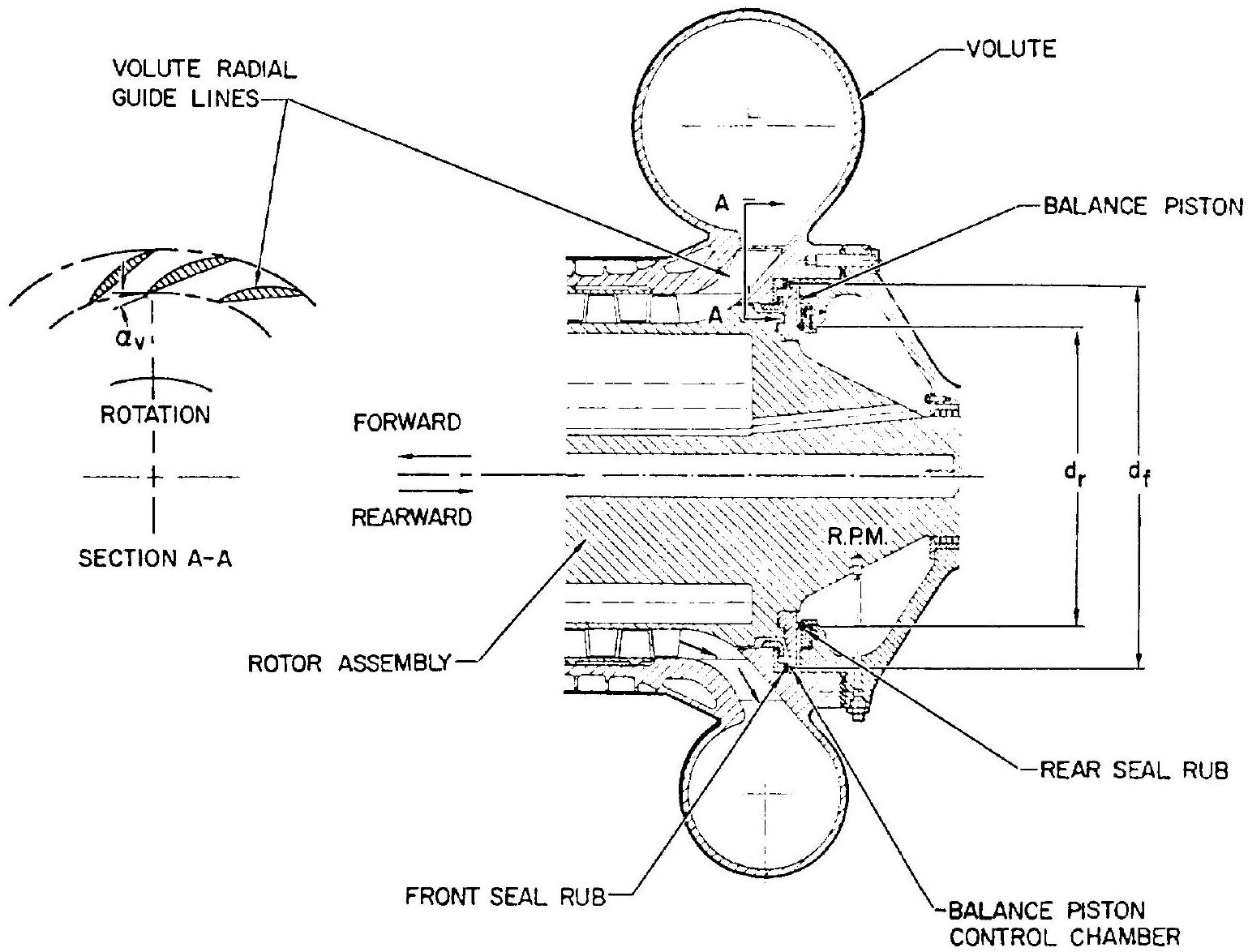 Figure 6-54.-Axial-flow pump volute casing and balance piston arrangement.