6.1 ELEMENTS OF TURBOPUMP PROPELLANT FEED SYSTEMS
The supply of propellants to the inlet of the pumps at required minimum pressures is customarily considered the responsibility of the vehicle propellant system and thus of the vehicle designer. The main function of the turbopump feed system then is to raise the pressure of the promollante received from the vehicle tanks and deliver them to the main thrust chamber, through ducts and valves, at pressures and flow rates commensurate with rated engine operation. A turbopump feed system may consist of the following basic elements: (1) Propellant pumps (2) Turbine(s) to drive them (3) A power source for the turbine(s) during engine start as well as main stage) (4) Speed reduction gear transmissions (if any) (5) Lubrication system for bearings and gears (if any) (6) Shaft-speed pickup for instrumentation and for safety purposes (overspeed cutoff) (7) Accessory drives (if any) (8) Propellant inlet and discharge ducts (if any) (9) Turbopump mounts
Propellant Pumps
The principal requirements of a rocket engine propellant pump are reliability, optimum speed, light weight, high delivery rate at maximum pressure head, smooth flow for a wide range of operating conditions, and high efficiency. The most widely used pump types are centrifugal (or radial) flow, axial flow, and mixed flow pumps. Centrifugal pumps are generally designed with a single stage, while axial pumps are primarily of multistage design. However, multistage centrifugal pumps with crossover-type volutes have also been considered. Various pump configurations are shown schematically in figure 6-4.
- Centrifugal pumps.-Almost all operational rocket propellant pumps (except those for highflow, high-pressure liquid hydrogen applications) are of this type. They can handle large flows at high pressures efficiently as well as economically in terms of weight and size. The elements of a centrifugal pump are shown in figures 6-5,
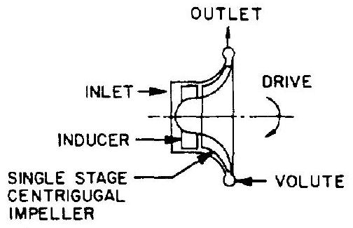 SINGLE STAGE CENTRIFUGAL PUMP
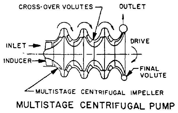
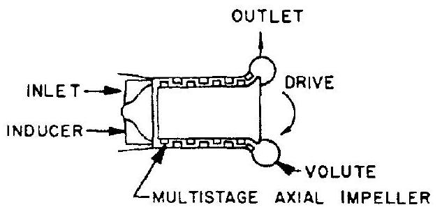
MULTISTAGE AXIAL PUMP
Figure 6-4.-Schematics of various pump configurations. , and 6-48. Centrifugal pumps, like other steady-flow rotating machinery, consist essentially of two basic elements: the rotor and the stator. Their working principle is the acceleration of the fluid flow by imparting kinetic energy to it in the rotor and then decelerating or "diffusing" it in the stator. This results in increased fluid pressure head. The rotor assembly usually includes an inducer, an impeller, and a shaft. The stator assembly consists of a casing with stationary diffuser vanes, a volute with discharge outlet, shaft bearings, and seals.
An inducer is an axial-flow-type impeller. Its main function is the increase of the static pressure of the entering fluid sufficiently to permit normal operation of the main impeller. An inducer can reduce the pump inlet pressure net-positive suction head (NPSH) requirements
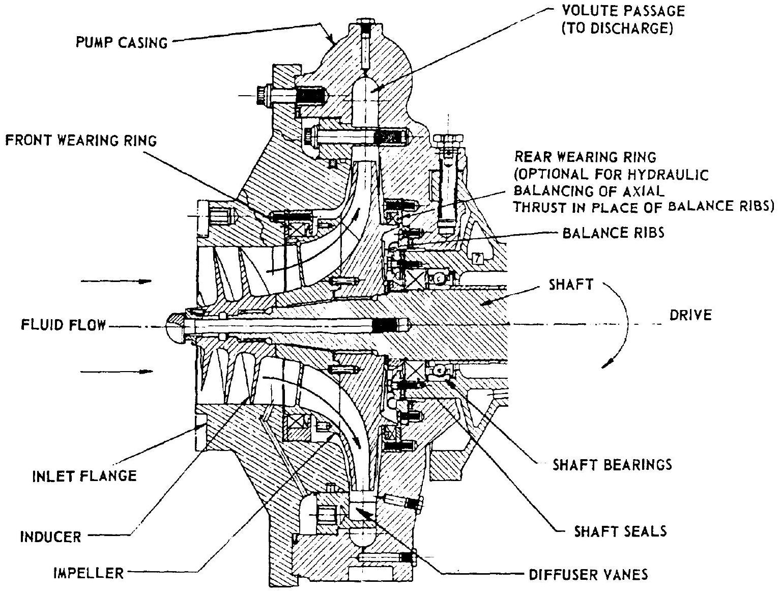 Figure 6-5.-Elements of a centrifugal-flow pump.
substantially. The impeller of a centrifugal (or radial) pump basically is a rotating wheel with radial vanes. Fluid is admitted axially to the impeller which, when rotating in an enclosure, ejects it at the periphery with increased velocity (fig. 6-5).
The primary functions of the pump stator assembly are: diffusing (i.e., decelerating) the fluid to convert the velocity head into pressure head, collecting and redirecting the fluid to the pump discharge outlet, and providing structural support and a pressure enclosure for the pump. The main function of the wearing rings shown in figure 6-5 is to provide axial thrust control and to minimize internal leakage, or circulating of the fluid between the high-pressure (discharge) and the low-pressure (inlet or suction) zones. External leakage along the shaft is prevented by the use of dynamic shaft seals. 2. Multistage centrifugal pumps.-For higher pressure rises, multiple-stage centrifugal pumps can be designed if a single stage proves limited. The basic construction of a multistage pump is similar to that of a single-stage pump, except that proper channeling of the fluid between stages is added. 3. Multistage axial pumps.-This design is well suited to liquid hydrogen service which entails the problems of extremely low fluid temperature and density. Low fluid density results in high-volume flow and in high pressure-head rise requirements. For applications at either flow rates higher than or pressure-head rises above 1400 psi , a multistage axial flow pump is generally superior with respect to construction and performance.
Elements of an axial flow pump are shown in figures , and . The rotor assembly
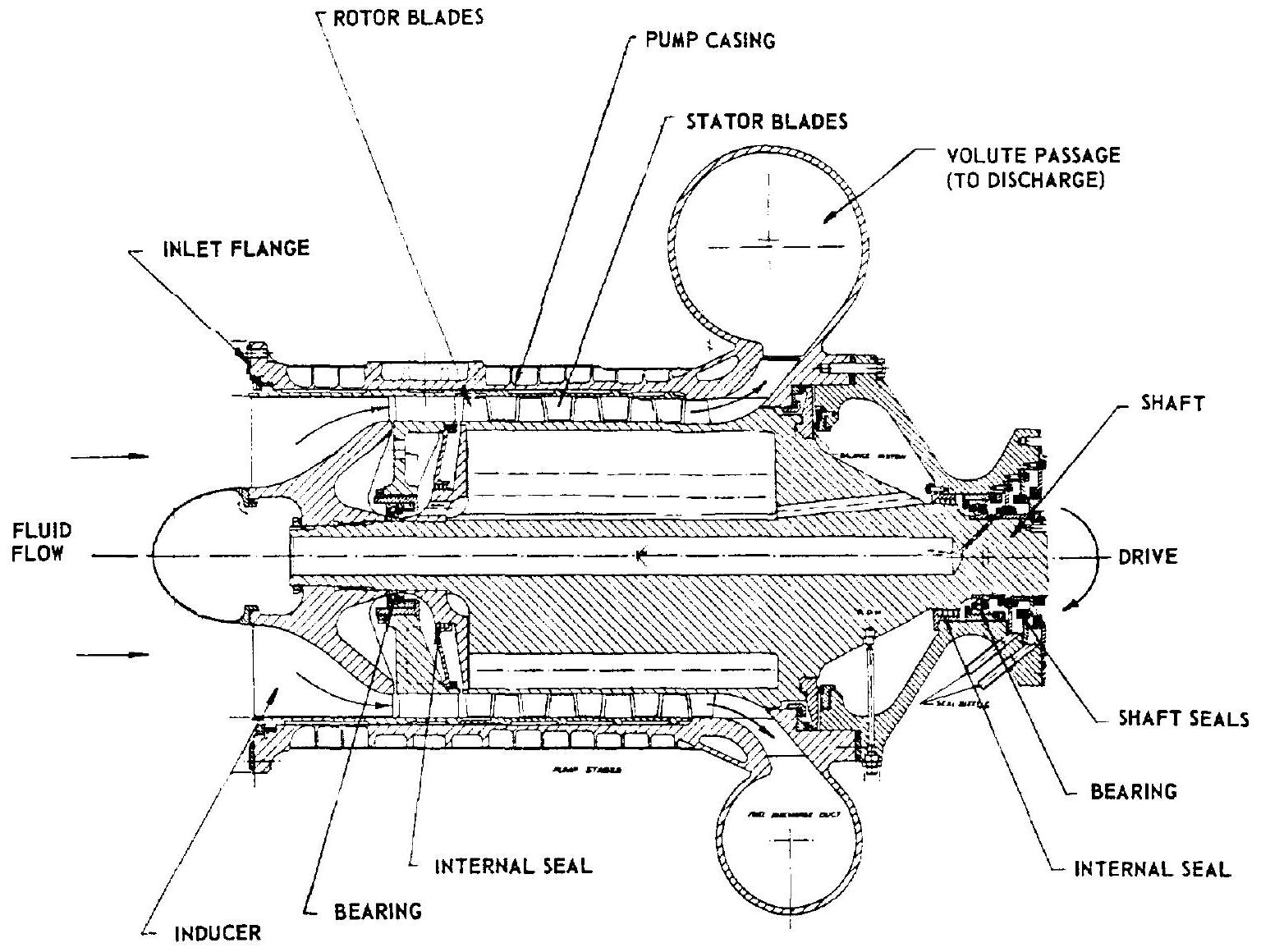 Figure 6-6.-Elements of an axial-flow pump.
consists of an inducer, a cylindrical rotor with multiple rows of rotating blades, and a rotor shaft. The stator assembly includes a cylindrical casing with rows of stationary blades spaced between inducer and rotating blades, a volute casing, bearings, and seals.
An inducer is placed at the pump inlet to supply the fluid to the main-pump section at the required pressure and velocity. Both rotor and stator blades have a hydrofoil shape. The main function of the rotor blades is to accelerate the flow relative to the stator and thus to increase the kinetic energy of the fluid, while the stator blades, acting as diffusers, convert the velocity head of the fluid into pressure head. However, the velocity vector of the fluid in the axial direction is kept constant throughout the various stages of the pump.
Turbines
The turbines which provide shaft power to the propellant pumps derive their energy from the expansion of a high-pressure, high-temperature gas to lower pressures and temperatures. The basic elements of a turbine are shown in figures , and . Turbines can be divided into two major types: impulse turbines and reaction turbines. Impulse turbines can be either single or multiple stage. Reaction turbines are usually multistage. Various turbines employed in rocket engine applications are described as follows:
- Single-stage, single-rotor impulse turbine.This turbine consists of a single-rotor disk or turbine wheel to which is attached a row of turbine blades or buckets. Gas is fed to the rotating blades through stationary nozzles (fig. 6-8).
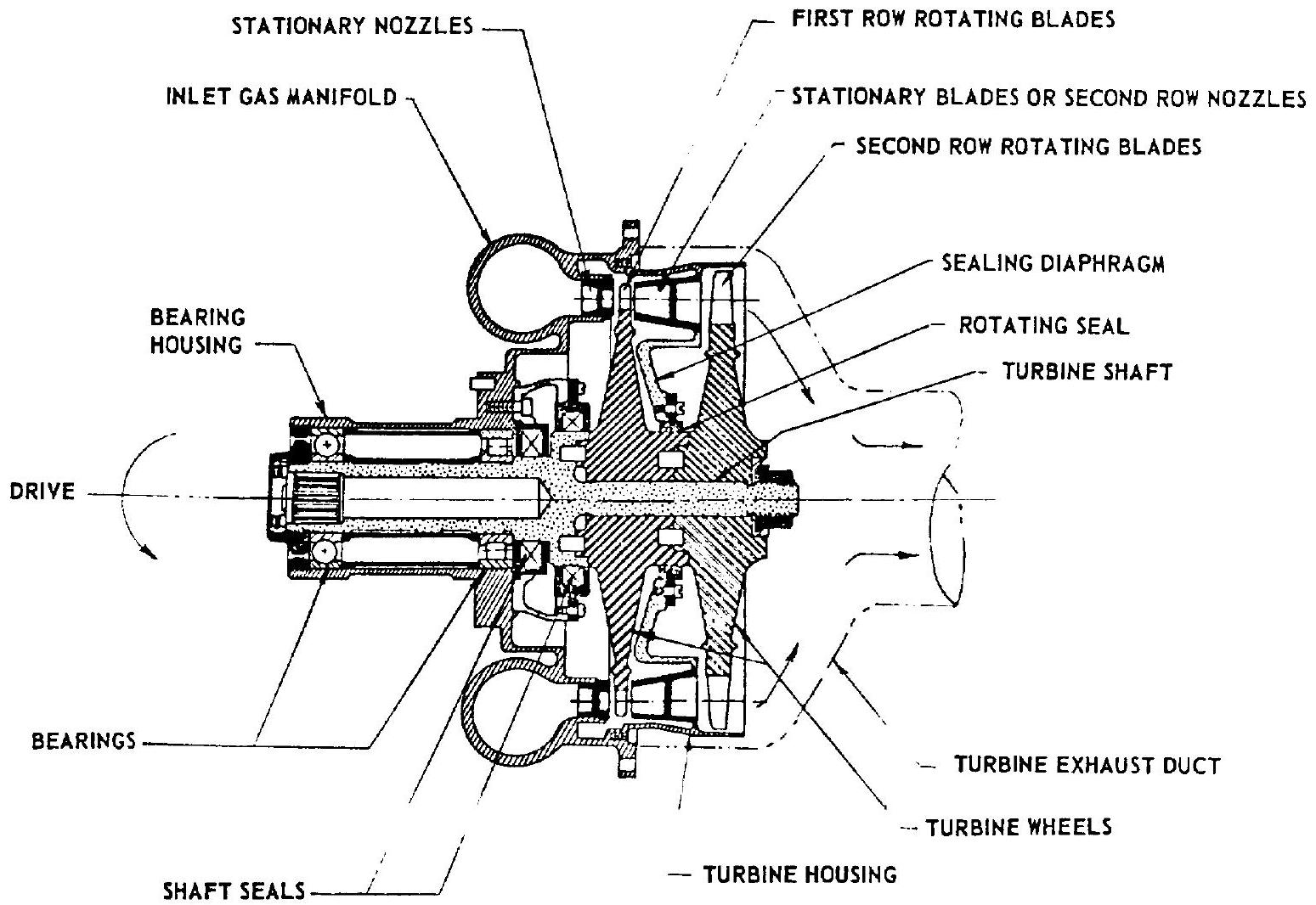 Figure 6-7.-Elements of a turbine.
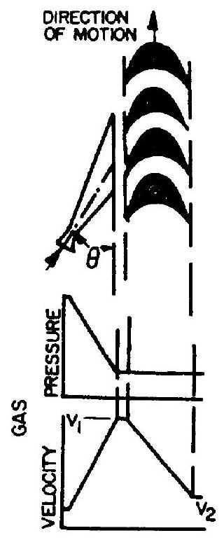 Figure 6-8.-Schematic of a single-stage, singlerotor impulse turbine.
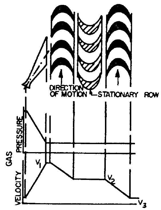 Figure 6-9.-Schematic of a single-stage, tworotor, velocity-compounded impulse turbine.
In the nozzles, the gas pressure is converted into kinetic energy (velocity head) with attendant static pressure drop. The gas flow velocity is maximum upon entering the rotating blades, where the kinetic energy of the gas is imparted to the turbine rotor as mechanical energy of rotation. Ideally, the static pressure of the gas remains constant when it passes through the rotating blades (except for the effects of friction). 2. Velocity-compounded impulse turbine.Figure 6-9 shows a schematic of this turbine type. Here, two separate rows of rotating blades instead of one are used to transfer the kinetic energy of the gas discharged from the set of stationary nozzles. A row of stationary blades is placed between the wheels to guide the gas into the second set of moving blades. This principle is credited to Curtis who originally developed it. Ideally, the entire pressure drop occurs in the stationary nozzles. The gas velocity decreases during passage through the first row of rotating blades, remains constant through the stationary blades, and decreases further as it passes through the second rotating row. Velocitycompounded turbines are considered single stage, since only one pressure step is involved. 3. Pressure-compounded impulse turbine.-As shown schematically in figure 6-10, the expansion of the gas is accomplished in steps, through two or more rows or stages of stationary nozzles, each set being followed by a row of rotating blades. A design objective is that the velocity, and thus the kinetic energy, of the gas flow is the same at the entrance of each row of rotating blades. This results in equal energy transferred to each rotating blade row, while the pressure drop in each stationary nozzle row will vary. Since the pressure is greater in region than in region , it is necessary to separate the stages by a sealing diaphragm to prevent bypass flows (fig. 6-7). However, because of clearances required at the rotating seal between diaphragm and turbine shaft, some losses do occur at this point due to leakage from stage to stage. 4. Reaction turbine.-The main difference between an impulse turbine and a reaction turbine (shown schematically in fig. 6-11) is that in an impulse turbine no static pressure drop occurs (no expansion) while the gas passes through the rotating blades, whereas in a reaction turbine the pressure does drop (expansion occurs). Both
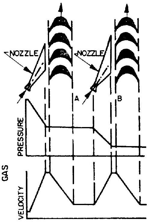 Figure 6-10.-Schematic of a two-stage, pressurecompounded impulse turbine.
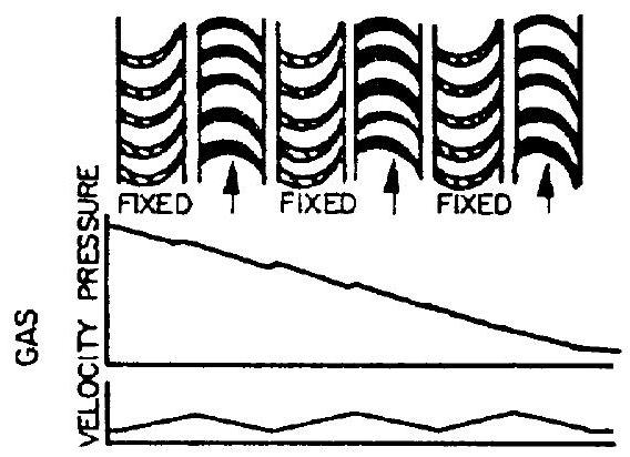 Figure 6-11.-Schematic of a reaction turbine.
impulse and reaction wheels are driven by a change in momentum of the gas. In a pure reaction-type turbine, the driving force is derived entirely from the reaction due to gas expansion within the rotating blades (similar to the gas expansion in a rocket nozzle). In actual reaction turbine designs, however, a portion of the driving force is derived from impulse due to gas impingement on the rotating blades.
Turbine Power Sources
In most applications the turbine is driven by gas produced in either bipropellant or monopropellant gas generators. Other turbine power sources have also been used, such as "tapoff" and "topping" systems. Typical turbine power sources are shown in figure 6-12 and are described briefly as follows:
- Bipropellant gas generator.-This is the most widely used system since it has the advantage of using the engine main propellants.
- Monopropellant gas generator.-This provides the simplest gas-generating system. However, it requires a third propellant if neither one of the main propellants is suitable for monopropellant application.
- Thrust chamber bleed.-This is applied in "tapoff" engine systems. Gases are bled off directly from the main combustion chamber to drive the turbine.
- Topping.-In a topping cycle, such as with a hydrogen-fueled engine system, the heated hydrogen gas emerging from the thrust chamber cooling jacket is used as the turbine working fluid before being injected into the main combustion chamber. In systems using a monopropellant as one of the main propellants, the monopropellant can be decomposed and used to drive the turbine prior to injection into the main combustion chamber. Topping gas turbine drives render the highest possible theoretical cycle efficiency.
- Dual combustion.-The entire fuel flow reacts with a portion of the oxidizer in a bipropropellant gas generator and thus provides the gas to drive the turbine. The usually fuel-rich exhaust gas is then ducted into the main combustion chamber and reacts with the balance of the oxidizer. Dual combustion cycle efficiency equals that of the topping cycle.
For most systems, an auxiliary power source is required during engine start to drive the turbine until the main power source takes over. The energy and its rate of delivery required for the start transient depend to a large extent on the engine system design. Several common turbine power sources for engine start are as follows:
- Monopropellant.-In systems using a liquid monopropellant gas generator, the fluid is supplied by an independently pressurized tank, such as in the German V-2 engine. Thus, no additional turbine power source for engine start is required.
- Bipropellant start tanks.-In a system using a liquid-bipropellant gas generator, fed from the main propellant system, bipropellant
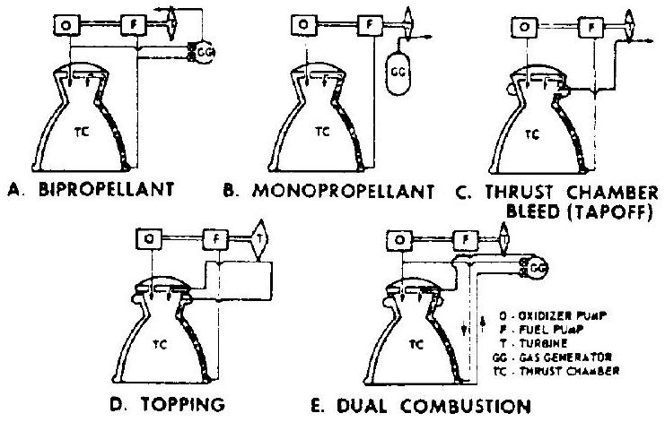 Figure 6-12.-Typical turbine power sources.
start tanks pressurized to up to 90 percent of rated pump outlet pressures supply the propellants to the gas generator during engine start until main propellant pump discharge pressures build up. In some applications (first stages), the start tanks have been made a part of the groundsupport equipment. 3. Main propellant tanks.-Experimental engine systems have been successfully started with the propellants supplied directly from the vehicle main propellant tanks, thus initiating gas generator and main thrust chamber operation until pump "bootstrap" occurred. In a hydrogen-fueled topping cycle engine, hydrogen vapor is used under tank head pressure to start the turbine directly. 4. Stored gas.-Stored gas under high pressure has been used to spin the turbine during engine start. In the case of hydrogen-fueled engines, hydrogen gas stored in a rechargeable bottle is used to drive the turbine during initial as well as restarts. 5. Solid propellant gas generator.-Solid propellant gas generators or turbine spinners, as shown in figure 4-49, have also been widely used to power turbines during engine start.
Turbopump Drive Arrangements
The specific type of coupling between turbine and pumps depends not only upon the propellants being pumped but also on the design of the overall engine system. Various turbopump drive arrangements are shown schematically in figure 6-13. Where a single turbine directly drives both propellant pumps through a common shaft, the turbine can be located either on the shaft end
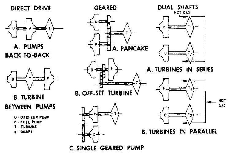 Figure 6-13.-Principal turbopump drives.
(with back-to-back pump arrangement), or between pumps. In this case both pumps and turbine will operate at the same shaft speed. Geardirven turbopump arrangements include: the pancake type, which uses different reduction gears and is applied where there are speed differentials between pumps and turbine; the offset turbine, with both pumps on one shaft but driven through a gear train; and the single-geared pump where one pump is mounted with the turbine on the same shaft, while the other is driven through a reduction gear. Dual-shaft turbopump arrangements with pump and turbine for each propellant on separate shafts include: two gas turbines in series with the discharge gas from the first turbine driving the second turbine; and two gas turbines in parallel, both receiving gas directly from the power source.
Description of Developed Turbopump Systems
Figures 6-14 and 6-15 illustrate a typical liquid bipropellant rocket engine turbopump system. It was developed for a 188000 -pound-thrust LOX/RP-1 booster engine. Figure 6-14 shows the major elements of this turbopump design. Figure 6-15 is a cutaway view of an actual assembly with the inlet elbow ducts attached. This assembly is a dual-pump unit consisting of an oxidizer pump, a fuel pump, a reduction gearbox, an accessory drive adapter, and a turbine. The turbine is started by hot gases from a turbine spinner (solid propellant gas generator) and powered from a liquid propellant gas generator during mainstage. The turbine shaft drives a series of reduction gears, which in turn drive the pump shaft. The turbopump gears and bearings are cooled and lubricated either by a separate oil supply system, or by a fuel additive subsystem (fig. 6-17). During mainstage operation, the turbopump supplies oxidizer and fuel to the main thrust chamber as well as to the gas generator at the required pressures and flow rates. Operating characteristics and materials of construction for this turbopump are listed in table 6-1.
Both oxidizer and fuel pumps are of singleentry, centrifugal-flow type. They are mounted back to back on a common shaft, one on each side of the gearbox. The fuel pump is bolted to the gearbox, while the oxidizer pump is secured to it by radially inserted steel pins. These pins allow the oxidizer pump housing to expand and contract during extreme temperature changes without distortion and misalinement. Each pump has an axial-flow inducer, a radial-flow impeller with backward curved vanes, stationary diffuser vanes, and a volute. The propellants pass from the inducers to the guide vanes in the impeller inlets through the impeller rotor vanes into stationary diffuser vanes in the pump casing and into the pump volutes. The diffuser vanes assure uniform pressure distribution and reduction of fluid velocity around the impellers. Balance ribs are provided on the back side of the impellers to neutralize pump shaft axial thrust.
The gearbox includes a series of full-depth reduction spur gears with integral bearing inner races, gear carrier and main shaft bearings. accessory drives, pump shaft bearing seals, and a bearing heater on the oxidizer pump shaft. A drain manifold is provided for horizontal drainage. The gears reduce the speed of rotation between turbine and pump shaft by an overall ratio of 4.88 to 1 . Details of typical turbopump gears and bearings are shown in figure 6-16. The pump shaft turns clockwise as viewed from the oxidizer pump. The sequence of power transmission is as follows: turbine to high-speed pinion gear, to intermediate shaft gear, to intermediate pinion gear, and to pump shaft gear. Power is also transmitted to a main accessory drive gear from a drive pinion gear mounted on the intermediate gear shaft.
The turbine is an impulse-type, two-stage pressure-compounded unit (fig. 6-10). It is bolted to the fuel pump housing and consists of hot gas inlet manifold, stationary nozzles and
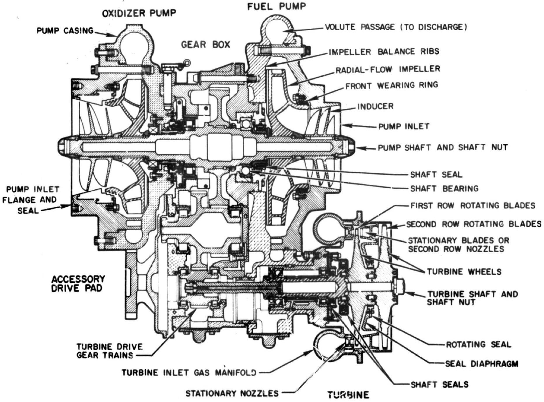 Figure 6-14.-Major elements of a typical turbopump.
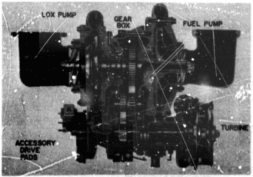 Figure 6-15.-Cutaway view of a turbopump assembly.
blades, first- and second-stage turbine wheels, a turbine shaft, and a splined quill shaft connecting the turbine shaft to the high-speed pinion gear. The turbine shaft is supported on the inboard side by a ball bearing; on the outboard side, by a roller bearing. Carbon-ring shaft seals are used to prevent hoi-gas leaks. The turbine inlet manifold distributes the gases to the first row of stationary nozzles which, in turn, distribute the gases to the first row of rotating blades. When leaving these, the gases again increase their velocity when passing through the second row of stationary nozzles. They finally pass through the second row of rotating blades and leave the turbine through an exhaust duct. A sealing diaphragm between the first and second turbine wheel prevents the hot gas from bypassing the second row of stationary nozzles.
In later systems, a fuel additive blender unit (fig. 6-17) was substituted for the oil lubrication system to increase reliability and to reduce weight by eliminating the separate oil tank, its prossurizing equipment, plumbing, and controls
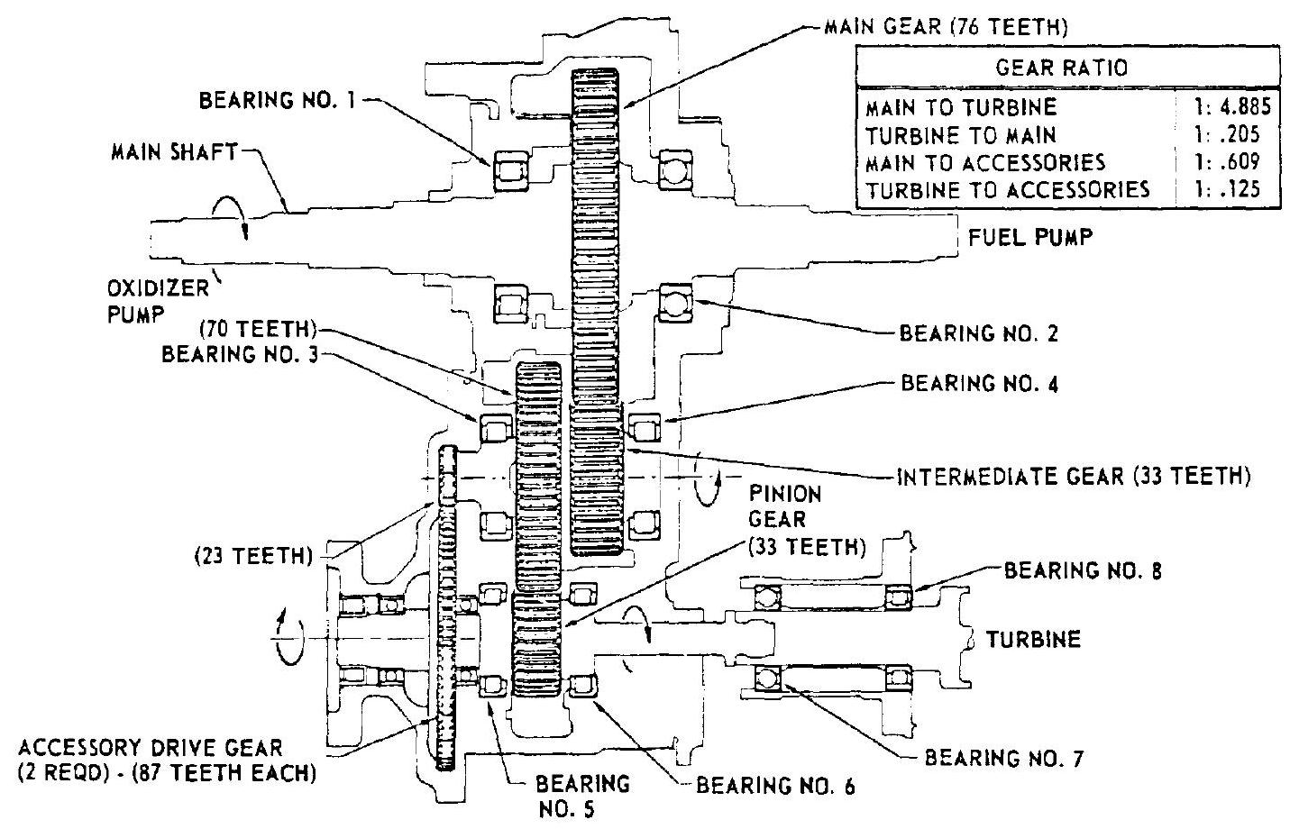 Figure 6-16.-Typical turbopump gears and bearings.
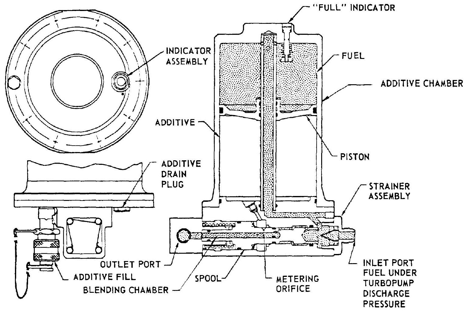 Figure 6-17.-Fuel additive blender unit.
Table 6-1.-Operating Characteristics and Materials of Construction for the Turbopump Shown in Figure 6-14
| Oxidizer | Fuel | |
|---|---|---|
| Pumps: | ||
| Fluid | Liquid oxygen | RP-1 |
| Inlet density | ||
| Inlet pressure (total) | 80.0 psia | 57.0 psia |
| Discharge density | ||
| Discharge pressure (total) | 915.2 psia | 1023.0 psia |
| Pressure rise in pump | 835.2 psi | 966.0 psi |
| Pump developed head | 1696.2 ft | 2751.0 ft |
| Volume flow | 3257.4 gpm | 2007.6 gpm |
| Flow rate | ||
| Shaft speed | 6537 rpm | |
| Efficiency | 75.5 percent | 72.1 percent |
| Shaft power | 2117 bhp | 1565 bhp |
| NPSH required | 35.0 ft | 35.0 ft |
| Casing material | TENS 50-T6 aluminum alloy sand casting | |
| Inducer material | 7075-T6 aluminum alloy die forging | 2024-T351 aluminum alloy plate |
| Impeller material | TENS 50-T6 aluminum alloy sand casting | 9669-48230-3 aluminum alloy sand casting |
| Shaft material | 4340 alloy steel | |
| Bearing material | 9310 alloy steel | |
| Turbine: | ||
| Inlet gas pressure (total) | 597.6 psia | |
| Exit gas pressure (static) | 32.86 psia | |
| Pressure ratio: Total inlet/static exhaust | 18.21 | |
| Inlet gas pressure (static) | 517.8 psia | |
| Inlet gas temperature | ||
| Exit gas temperature | ||
| Gas flow rate | ||
| Brake horsepower | 3793 hp | |
| Shaft speed | 31740 rpm | |
| Efficiency | 66.2 percent | |
| Housing material | Hastelloy "B" | |
| Nozzle block material | Hastelloy "B" | |
| Wheel material | Timken alloy 16-25-6 AMS-5727 steel | |
| Shaft material | 4340 alloy steel | |
| Bearing material | 9310 alloy steel | |
| Gearbox: | ||
| Reduction speed ratio | 1/4.855 | |
| Gearbox material. | TENS 50-T6 aluminum alloy sand casting | |
| Gear and-shaft material | 9310 alloy steel die forging | |
| Bearing material | 9310 alloy steel |
previously required. The blender works on the principle of adding a small amount of a chemical to the fuel tapped off through metering orifices at the fuel pump outlet and of using this mixture as the lubricant. The fuel entering the blender inlet port is admitted to the top side of the additive chamber and to the blending chamber. The fuel pressure causes the piston to displace and to inject a proportionate amount ( 2.75 percent) of additive into the fuel flowing through the blending chamber. The mixture then flows to the turbopump where it lubricates and cools the gears and bearings.
Figure 6-18 and table 6-2 illustrate another turbopump system. It was developed for a pound-thrust aircraft superperformance rocket
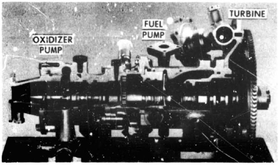 Figure 6-18.-Cutaway view of an aircraft rocket turbopump assembly.
engine (shown schematically in fig. 4-60). Pumped fluids are 90 percent hydrogen peroxide and JP-4 fuel. The turbopump consists of two centrifugal pumps mounted back to back on a single shaft which ie directly driven by a singlestage, single-rotor impulse turbine. The shaft is supported by antifriction bearings located between the two pumps, and just forward of the overhung turbine. The bearings are lubricated by a pressure-fed lube oil system. Inducers are used on both pumps to permit operation at a low
Table 6-2.-Aircraft Rocket Turbopump Operating Characteristics
| Oxidizer | Fuel | |
|---|---|---|
| Pumps: | ||
| Fluid | JP-4 | |
| Density | ||
| Inlet pressure (total) | 25 psia | 15 psia |
| Discharge pressure (total) | 862 psia | 657 psia |
| Pressure rise in pump | 837 psi | 642 psi |
| Pump developed head | 1382 ft | 1910 ft |
| Volume flow | 106.8 gpm | 26.4 gpm |
| Flow rate | ||
| Shaft speed | 30000 rpm | |
| Efficiency | 60 percent | 40 percent |
| Shaft power | 87 bhp | 25 bhp |
| Turbine: | ||
| Inlet gas pressure (total) | 510 psia | |
| Exit gas pressure (static) | 55.5 psi a | |
| Pressure ratio: | ||
| Total inlet/static exhaust | 20 | |
| Inlet gas temperature | ||
| Extaast gas temperature | ||
| Gas flow rate | ||
| Brake horsepower | 112 hp | |
| Shaft speed | 30000 rpm | |
| Efficiency | 40 percent |
NPSH. Pump inducers, impellers, shaft and cast housings are fabricated from 300 series stainless steel. Turbine manifold, housing and nozzle blocks form an integral Hastelloy-X weldment. The turbine wheel is made of Timken alioy.