5.2 STORED GAS SYSTEMS
Stored gas pressurization systems are widely used in numerous combinations. The gas is usually stored in a vessel at pressures ranging from 3000 to 5000 psi and supplied to the propellant feed system at a specified pressure level controlled by a regulator. These systems have achieved a high level of reliability. In earlier systems, compressed nitrogen gas was frequently used or even air (German V-2), mainly for logistics and supply reasons. As it became more readily available, helium gas found increased usage because of its substantially lower molecular weight and thus reduced total pressurant weight, and its superiority as an inert agent, with very low boiling point. For hydrogen-fueled engine systems, reliable compressed hydrogen gas systems have been successfully developed. In general, the most important design requirements for a stored gas system are: low molecular weight of the gas, high gas density under storage conditions, minimum residual gas weight, and high allowable stress-to-density ratio of the storage vessel material. Since helium systems are now the most widely used ones, the following discussions will be based on them.
Discussion of Commonly Used Configurations
- Helium system without heating.-This pressurization system is shown schematically in figure 5-1. It consists of a high-pressure storage vessel, a start and shutoff valve, and a pressure regulator. Regulated helium is ducted directly
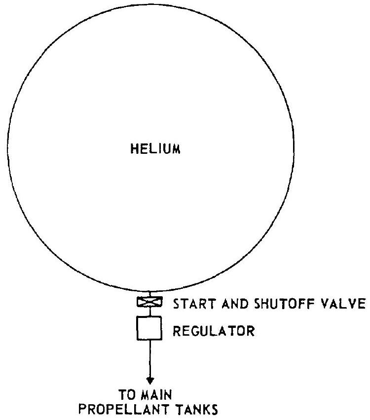 Figure 5-1.-Helium pressurization system without heating.
to the main propellant tanks. This has the advantage of great simplicity. However, the weight of the system is relatively high because of the lower temperature and thus lower specific volume of the gas. 2. Helium system using thrust chamber heat exchangers.-This system, which is used in the design for the A-3 and A-4 stage propulsion systems, consists of a high-pressure helium storage vessel, a start and shutoff valve, manifolded thrust chamber heat exchangers, and a pressure regulator. A typical schematic is shown in figure 5-2. The heat exchangers are part of the thrust chamber divergent nozzle section and absorb heat from the thrust chamber combustion process. From overall performance and weight considerations it is considered preferable to locate the heat exchanger in the high-pressure portion of the system. The volume increase of the gas due to heating reduces the mass required for tank pressurization. However, a considerable quantity of cold, high-density helium still remains in the storage vessel at the end of the system operation. 3. Helium cascade system.-The cascade system shown schematically in figure 5-3 is an
1
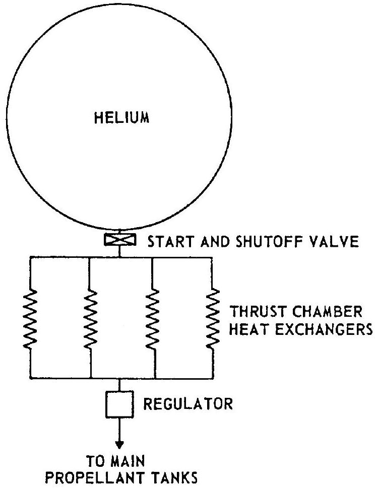 Figure 5-2.-Helium pressurization system using thrust chamber heat exchangers.
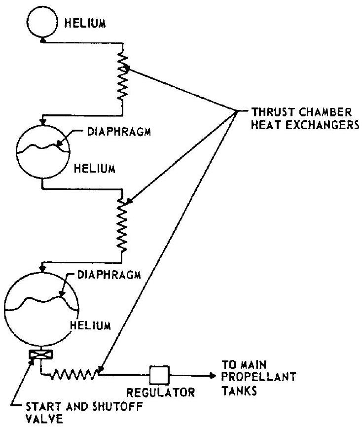 Figure 5-3.-Helium cascade system.
all-helium pressurization system designed to minimize the weight penalty resulting from cooling of the helium during expansion. System components include helium storage vessels of equal high-pressure level but of different sizes, two of which are divided internally by a flexible diaphragm, three thrust chamber heat exchangers, a start and shutoff valve, and a pressure regulator. During operation of the system, helium flows from the first and smallest vessel, through a heat exchanger, and displaces completely the helium in the intermediate vessel. The helium in the intermediate vessel in turn flows through a second heat exchanger and completely displaces the helium in the last and largest vessel. The latter flows through a third heat exchanger and pressurizes the main propellant tanks. At the end of the operation, only the small storage vessel contains low-temperature, high-density helium, while the two large storage vessels contain relatively warm low-density helium. This contrasts with the preceding systems in which one large storage vessel remains partially filled with low-temperature, high-density helium. The disadvantages of cascade systems are high weight and complexity. 4. Helium system with heating inside the storage vessel.-This system is shown schematically in figure 5-4 and consists of a high-pressure helium storage vessel containing a heat exchanger or other heat-generating device mounted internally, a start and shutoff valve, and a pressure regulator. This system provides higher temperature helium to the main propellant tanks, simultaneously assuring relatively warm residual gas in the storage vessel. Disadvantages are the need for larger and more complex high-pressure storage vessels and the possibility of control problems during operation.
For the pressurization of liquid hydrogen propellant tanks, stored hydrogen gas can be used in place of helium for the systems described above.
Calculations for Stored Gas Requirements
The design calculations discussed in section 5.1 apply only to the net or effective quantity of gas required to pressurize the propellant tanks. However, the gross weight of the stored gas required for a given system depends also on the
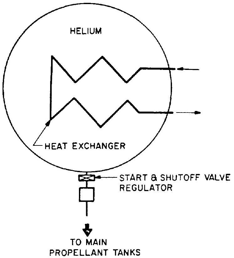 Figure 5-4.-Helium pressurization system using heaters in storage vessel.
system design, on the expansion process during operation, and on the environmental temperature range within which the system must function. Based on conditions at systems burnout, the total or gross stored gas requirement can be expressed by the following correlation:
| Stored gas gross |
|---|
| requirement |
| :---: |
| requirement |
A parameter to define these additions is the pressurant use factor, defined as the ratio of gross stored gas requirement or initial gas weight in the storage vessel to the net weight of pressurant utilized:
The lowest pressure level in a storage vessel required to safely operate the pressurization system is determined by the individual system pres-
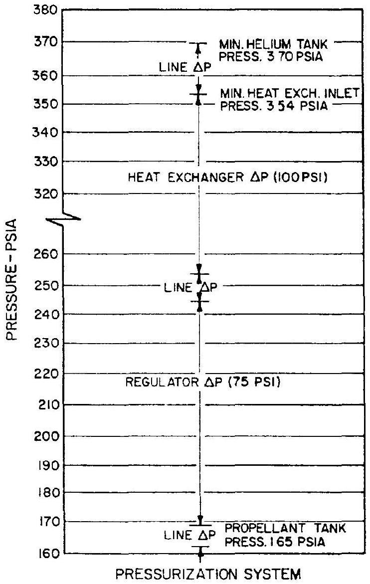 Figure 5-5.-Estimated pressure drops for A-4 stage oxidizer tank pressurization system.
sure drops. Figure shows estimated pressure drops for the stored helium pressurization system with thrust chamber heating which was selected for the A-4 stage engine oxidizer tank. In addition, a safety margin is usually provided. In this case, the mission is assumed to be completed when the storage vessel pressure decays to 400 psia .
If a heating source is provided inside the vessel, as shown in figure 5-4, the expansion process of the gas within would be polytropic. For a system without heating inside the storage vessel, the expansion process of the gas can be assumed to be isentropic; i.e., no heat is transferred between gas and vessel walls. From equation (1-13) the following correlation can be derived to calculate the final gas temperature in the storage vessel:
where initial helium temperature in the vessel, final helium temperature in the vessel, initial helium pressure in the vessel, psia final helium pressure in the vessel, psia exponent for the polytropic expansion process The exponent is estimated during analytical treatment and verified experimentally. For isentropic expansion of helium, .
For most analyses it has been found adequate to assume an adiabatic flow process through regulator and lines. It is a characteristic of this process that the total (or "stagnation") temperature remains constant. Since the gas essentially comes to rest in the propellant tank and no further compression takes place following initial propellant tank pressurization, it is assumed that propellant tank temperature is equal to heat exchanger outlet temperature.
If an operating temperature range is specified for a system, the lower temperature limit must be used to calculate the weight of pressurant required, while the upper limit determines the volume of the gas storage vessel for a given storage pressure. Thus, for a stated propellant tank net pressurant gas requirement, a wider environmental temperature range results in a heavier pressurization system, regardless of the expansion process followed by the gas.
Sample Calculation 5-2
The following data are given for the stored helium pressurization system of the A-4 stage oxidizer tank:
Temperature range in the storage vessel at system start, Storage vessel pressure at system start, 4500 psia Pressure in the storage vessel at system burnout, 400 psia
Volume of the helium lines downstream of regulator, Volume of heat exchangers, Volume of lines between storage vessel, heat exchangers and regulator, negligible Pressurant reserve, 2 percent Assuming an isentropic expansion process, calculate the following: (a) Oxidizer tank pressurant gross weight, storage-vessel volume, and use factor, for case (a) of sample calculation (5-1). (b) Oxidizer tank pressurant gross weight, storage-vessel volume, and use factor, for case (b) of sample calculation (5-1). (c) Oxidizer tank pressurant gross weight, storage-vessel volume, and use factor for single start operation but without heat exchangers. (d) Same as (c), but assuming a polytropic expansion process with in the storage vessel.
Solution
The following calculations establish the requirements for the oxidizer tank, which in the A-4 stage has the higher minimum storage pressure requirement. To this required pressurant mass and volumes for fuel tank pressurization, purges and valve actuations will have to be added. (a) A net pressurant requirement of 9.79 pounds is obtained from sample calculation (5-1), case (a). Temperature and pressure of the residual pressurant in the lines downstream of the regulators following shutdown are assumed to be the same as those of the propellant tank ullage gases at system burnout ( and 23760 psfa ). Residual gas weight in these lines then is
It is further assumed that the temperature of the residual pressurant in the heat exchangers is at run tank inlet conditions, or , and that the pressure is that of the residual helium in the storage vessel, or 400 psia . Thus a value of
is obtained for these residuals. Substituting the lower limit of the system operating temperature, and the initial and final helium pressures into equation (5-15), the temperature of the residual helium in the storage vessel at system burnout is obtained:
Using equation (5-13), the pressurant volume required for oxidizer tank pressurization can now be calculated, based on the lower storage temperature limit of :
Gross pressurant weight:
including 2 percent reserve. Using the upper start temperature limit ( ), the required volume of the storage vessel for oxidizer pressurization is calculated:
From equation (5-14), LOX tank pressurant use factor:
(b) From sample calculation (5-1), case (b), the net pressurant requirement is given as 10.65 pounds. Assuming temperature and pressure in the lines are the same as those in the propellant tank at system burnout ( and 23760 psfa ), residual gas weight in these lines is
The temperature of the residual pressurant in the heat exchangers is assumed to be at the run tank inlet level, or , and that the pressure is that of the residual helium in the storage vessel, or 400 psia . The gas weight in the heat exchangers then amounts to:
From equation (5-13), pressurant volume and mass are obtained, using the lower temperature limit:
Gross pressurant weight:
including 2 percent reserve. Required volume of the storage vessel:
Pressurant use factor:
(c) Without heat exchangers, the bulk temperature of helium in the propellant tank at system burnout can be expected to be the average of the initial and final helium temperatures in the storage vessel, or
Since this temperature is lower than the propellant temperature, no heat loss from pressurant to propellant is assumed. The net pressurant weight required may then be calculated by equation (5-1):
The weight of residual helium in the lines at system burnout:
From equation (5-13), pressurant volume and mass are obtained, based on the lower ambient temperature limit:
Gross pressurant weight =
including 2 percent reserve. The required volume of the storage vessel is
Pressurant use factor:
(d) The expansion process of helium in the storage vessel is assumed to be polytropic, with . From equation (5-14), the temperature of residual helium in the vessel at system burnout:
The helium bulk temperature in the propellant tank at system burnout:
The required net pressurant weight:
The residual helium weight in the lines at system burnout:
Pressurant volume and mass, based on the lower ambient temperature limit:
Gross pressurant weight:
including 2 percent reserve. The required volume of the storage vessel:
Pressurant use factor:
Design of Stored Gas System Components
Since system components can be expected to require relatively extensive development effort to achieve satisfactory performance and reliability, they require careful design considerations. This is especially true for large, high-pressure, lightweight, pressurant storage vessels, pressure regulators, and thrust chamber nozzle skirttype heat exchangers.
Storage Vessels
Because of the combined requirement of high pressure and light weight, pressurant storage vessels are generally spherical in shape and made of high-strength-to-weight materials. PH-15-7-MO stainless steel, 6Al-4V-titanium, and light aluminum liners wound with plastic filaments for strength, such as fiber glass, have been successfully employed as construction materials for the vessels. Design details for pressurant storage vessels will be further discussed in chapter VIII.
For weight estimates in preliminary designs, it is assumed that the vessel is made of two hemispherical shells, and that the thickness of the weld lands can be accounted for by assuming a 3 -inch-wide band of one-half the wall thickness placed over the weld seam. Hence, the total weight of the vessel can be estimated as:
where weight of the vessel, lb =inside diameter of the vessel, in maximum storage pressure, psia allowable working stress of the material, psi density of the material, It is of prime importance in the design of stored gas systems that the storage vessel be capable of containing the gas at high pressure for long periods of time without loss by leakage. Frequent checking of the storage pressure or recharging is undesirable in most applications.
Experimental data indicate that gases of low molecular weight such as helium and hydrogen will not leak through homogeneous metals such as good-quality, hot-rolled stock or forgings. However, they can leak through porous metals such as may exist in castings and in welded joints. Good welding workmanship and effective leakage inspection are most important in the fabrication of storage vessels.
Pressure Regulators
For most pressurization systems a regulator of high accuracy is a necessity. Regulation becomes particularly difficult if gases with temperatures higher than have to be handled, or if high flow rates or large pressure differentials are involved. Design detail of pressure regulators will be discussed in chapter VII. For some applications, a control system combining a pressure switch, a solenoid valve, and an orifice may be preferred.
Thrust Chamber Heat Exchangers
For helium systems using thrust-chamber heat
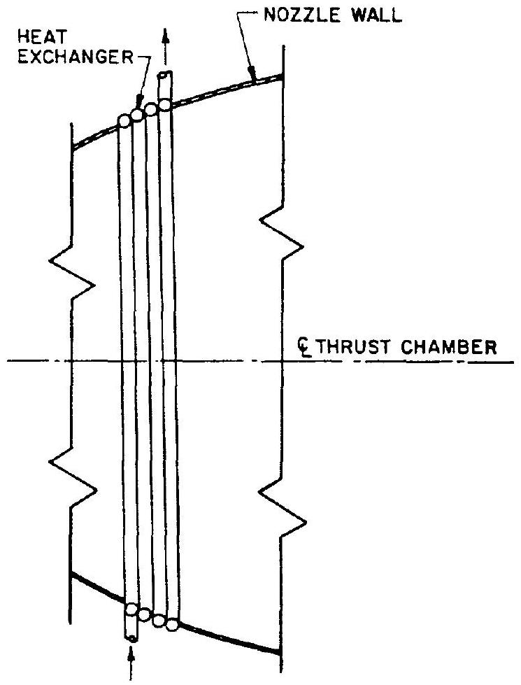 Figure 5-6.-Thrust chamber heat exchanger.
exchangers as shown in figure 5-2, the heat exchanger should be designed as an integral part of the thrust chamber expansion nozzle. As a rule, the heat exchanger is made of coiled tubing formed to fit the nozzle contour (fig. 5-6).
The combustion-gas side heat-transfer coefficient can be determined by methods described in chapter IV. The heat conducted through the wall of the heat exchanger is assumed to be totally absorbed by the pressurant helium, raising its temperature. The determination of the heliumside heat-transfer coefficient and the design of the heat exchanger tubing are similar to the regeneratively cooled tubular wall thrust chamber analyses. The number of tube turns for the heat exchanger is a function of the helium temperature rise required and of the heat exchanger location at the nozzle. The various operating parameters of a thrust chamber heat exchanger can be correlated by the following equation:
where
Heat exchanger design must consider that the temperature of the helium leaving the heat exchanger at any given time depends on the storage vessel exit temperature.
The choice of heat exchanger tube material must be made with consideration of its brazing compatibility with the main chamber nozzle wall. Firm attachment of the heat exchanger to the nozzle wall is mandatory, since heat exchanger efficiency depends on intimate contact. Selection of tube thickness must be based on pressure and thermal stress conditions.
Sample Calculation (5-3)
The following data are given for the design of the pressurant heat exchangers for the A-4 stage engine thrust chamber nozzle extension, when located at the station of area ratio , and used in parallel:
Helium flow rate through each heat exchanger, (considers requirements for both tanks and for other uses) Helium specific heat ratio, Helium specific heat at constant pressure, Mean temperature of helium at heat exchanger inlet, Mean temperature of helium at heat exchanger outlet, (from sample calculation (5-1), case (b)) Combustion-gas side adiabatic wall temperature, Combustion-gas side heat transfer coefficient, Calculate: (a) Heat exchanger tube dimensions, assuming it to be made of titanium alloy with the following physical characteristics, at a recommended maximum working temperature range of :
Minimum yield strength, Modulus of elasticity, Thermal conductivity, -sec-deg F/in Coefficient of thermal expansion, in/in-deg F Poisson's ratio, (b) Number of turns of the heat exchanger tubing.
Solution
(a) The wall temperature at given sections of the heat exchanger will vary directly with the bulk temperature of the helium in these sections. Maximum wall temperature occurs at the heat exchanger outlets. A mean combustion-gas side wall temperature ( ) at the outlets of is allowed. From equation (4-10), the heat flux at that section is:
A tube wall thickness ( ) of 0.05 inch is used. This will be checked further below for compatibility with pressure and thermal stresses. From equation (4-19), the mean helium-side wall temperature is
Using equation (4-20), the helium-side heat transfer coefficient is calculated as
Equation (4-15) permits determination of the Prandtl number of the flowing helium:
The viscosity of the helium according to equation (4-16) is:
From equation (4-25)
Inside tubing diameter, inch. Check for combined pressure and thermal stresses at the heat exchanger outlet (neglecting bending stress), using equation (4-27), and assuming bending stress due to discontinuities to be negligible
The combined pressure and thermal stresses at the heat exchanger inlet are now checked. It can be assumed that the difference between the combustion-gas side wall temperature and the helium bulk temperature remains approximately constant throughout the heat exchanger. Then: at the inlet (mean temperature) Heat flux at the inlet Combined stress at the inlet
Therefore, it is safe to use the selected tube size of 0.440 -inch inside diameter and 0.050 -inch wall thickness, with sufficient margin for the fact that the heat exchanger helium inlet temperature will be higher than the maximum at the beginning of the process. (b) From equation (5-17), the required effective area for each heat exchanger element
The nozzle diameter at area ratio of the A-4 chamber is:
Assuming 40 percent of the internal tube surface as the effective heat exchauger area, the number of heat exchanger tube turns required is: