9.5 DESIGN OF DUCTS FOR ROCKET ENGINES
Basic Design Considerations
Primary design considerations for various ducts used on rocket engines are:
- Fluid flow rate and system pressure drop.The size of the duct is determined largely by the required flow rate and permissible pressure drop of the flow system. An optimization must be made considering duct weight, pressure drop, and space, before finalizing the duct size.
- Working temperature and pressure of the fluid.-The solection of construction materials and structural design for ducts depends mainly on the working temperature and pressure level of the fluid, but also on chemical compatibility. Temperature also influences line flexibility and dact geometry.
- Duct joints.-The number and type of joints in a duct system are usually determined by system assembly and servicing requirements. All mechanically sealed joints should be reviewed, at various engine design and development phases, for their possible elimination or replacement by in-place, induction-brazed or welded joints. (See secs 5.3 and 9.4.)
- Line flexibility and geometry.-The required degree of flexibility in a duct system is dictated by component tolerance buildups, misalinements, and required freedom of movement to allow for temperature changes, dynamic loads, and engine gimbal effects, if any. This often determines the line geometry. In general, however, lines should be as short and straight as possible.
- Structural integrity.-The structural design of a duct system may involve a number of complex problems. This is especially true with ducts for elevated or very low temperatures, and requiring a high degree of flexibility. The design and fabrication of metal bellows for application in ducts is a highly specialized technology.
Duct Design for Minimum Pressure Drop
Techniques for fluid-flow pressure drop determination have been discussed in chapter VII. Equation (7-7) may be used to estimate the pressure drop of a straight duct section. Either equation (7-7) or (7-9) can be utilized to predict the pressure drops of other shapes, for which some experimental data are available.
Besides avoiding excessive flow velocities at various sections of a duct system, basic requirements ior minimum pressure drop are: constant flow area, smooth flow surfaces and path, minimum length, and few turns. In most duct designs, a certain number of turns is unavoidable. The design of these turns affects considerably the overall pressure drop of a duct system.
A turn may offer a large resistance to the flow if not carefully designed. Investigations show that the flow resistance in a bend with constant cross section is affected directly by its turning radius ratio (where radius of curvature of the axis of the duct, diameter or width of the duct) (see fig. 7-21). By increasing the turning radius ratio, large reductions in pressure drop are possible. Bends with a circular section are better than these with a square section. However, the square section may be much improved by changing it to a rectangle, so that the turn is made on the short side; that is, the loss can be decreased by increasing the rectangle aspect ratio (where width of the long side, width of the short side). For a duct with a rectangular section, therefore, a very efficient corner may be produced if the values of both the radius ratio and the aspect ratio are kept large.
This consideration should be applied in all cases where a sharp turning corner is unavoidable, such as the elbow-type turbopump inlet ducts shown in figure 6-15. Here, the loss around the sharp corner is due largely to the zero radius ratio. To reduce this pressure drop, guide vanes can be very effectively used. If the junctions of the duct walls on the diagonal are smoothed out and vanes added as shown in figure 9-18, the compartments so formed may be made to have a good radius ratio and a high aspect ratio. Since in most cases only a few vanes need to be added for high aspect ratios, the remaining problem is one of securing a good radius ratio.
The radius and aspect ratios of each compartment are increased as the gap/chord ratio is reduced (fig. 9-18). Theoretically, then, the corner pressure drop will decrease as the ratio S/C is decreased. However, each additional vane adds more surface area and blockage, and consequently tends to increase losses. The S/C ratio can be optimized in tests and ranges from 0.25 to 0.45 . Well-designed elbow-type sharp turns with guide vanes may have resistance coefficients as low as 0.1 to 0.2 (see eq. 7-9).
Duct Design for Flexibility
For most interconnecting ducts between two engine components, the required flexibility such as for misalinements and temperature changes can be achieved by placing one or two bellows sections in the line (figs. 9-4 and 9-5). These may be either restrained or unrestrained, depending on structural loading considerations. In ducts connecting two components involving large relative movements, a minimum of three flexible sections is required. The longitudinal axis of at least two of the bellows sections should be positioned at a right angle to one another. Restrained bellows are preferred.
The duct systems shown in figure illustrate a basic three-bellows arrangement as applied to gimbaled clustered engines. Figure 9-19 presents one of the frequently used design approaches for a relatively short duct system to facilitate large movements during gimbaling of an engine system. The three flexible sections are kept in the plane of the engine gimbal point. This results in minimum displacements of the sections for a given engine movement. Bellowstype universal joints (fig. 9-20) may be conven-
 Figure 9-18.-Elbow-type sharp turning duct with guide vanes.
 Figure 9-19.-Typical propellant supply duct designed for the flexibility required for engine gimbaling.
iently incorporated into this duct system by welding. These joints are made of stainless steel and will operate at cryogenic and elevated temperatures (up to ). The internal restraining mechanism is designed to give a smooth flow passage for low-pressure drop.
 Figure 9-20.-Typical gimbal-ring-type bellows universal joint designed and manufactured by Marman Division of Aeroquip Corp.
For higher pressure applications (over 200 psi), external wire braids or links may be used to restrain the bellows section. The braids can be made of stranded stainless-steel wires, about 0.012 -inch diameter. In extreme cases, more than one layer of braid should be used with regard to the high separation loads.
Structural Design of Bellows For Flexible Ducts
Most of the bellows used for flexible ducts in rocket engines are hydraulically formed by radi- ally expanding thin-wall tubing, at spaced intervals along its axis, coincident with an axial compression, to a configuration as shown in figure 9-21. Our discussion will be confined to this type of bellows. The various structural characteristics and design correlations of bel lows are presented using the following nomenclature (see figs. 9-21 and 9-22): = bellows wall-thinning correction factor ply interreaction factor ( 1.00 for 1-ply bellows, 0.90 for 2 -ply bellows, and 0.85 for 3-ply-or-more bellows) outside diameter of the bellows, in outside diameter of the convolution root of the bellows, in root-mean-square diameter of the bellows, in mean duct diameter, in modulus of elasticity of the bellows material, psi axial deflection of the bellows, in = equivalent axial deflection of the bellows due to pure bending, in equivaient axial deflection of the bellows due to parallel offset, in equivalent axial deflection of the bellows due to pure shear, in shear load, lb pressure separating load, lb G = shear modulus of elasticity of the bellows material, psi mean convolution height, in pitch of the bellows (axial length of a convolution), in free axial length of the bellows, in number of bellows convolutions number of bellows plys t thickness of the bellows wall, in axial length of the rigid duct section, in bending moment, in-lb = internal (or external) fluid pressure. psi eritical stability pressure of the bollows. psi axial spring rate of the bellows, bending spring rate of the bellows, degree parallel offset spring rate of the bellows, lb/in shear spring rate of the bellows,
 Figure 9-21.-Elements and various motions of bellows.
torsional spring rate of the bellows. degree bellows bulging stress, psi bellows hoop stress, psi bellows motion stress, psi bellows shear stress, psi bellows torsion stress, psi torsional moment, in-lb critical stability torque of the bellows, psi Poisson's ratio of the bellows material, in transverse deflection of the bellows, in bending angle of rotation, degrees torsional angle of rotation, degrees
- Thinning of the bellows wall.-Hydraulicformed bellows are usually made by starting with tubes of the same diameter as the bellows diameter at the root of convolution, . The typical thinning profile of a bellows wall starts with the original material thickness at the root of the convolution, and tapers approximately linearly to
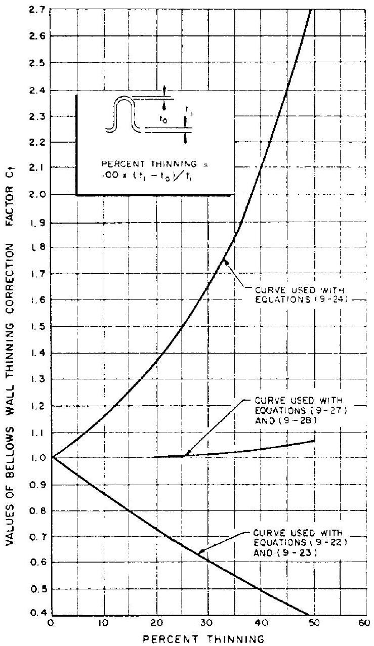 Figure 9-22.-Bellows wall thinning correction factor versus percent thinning.
the minimum thickness at the convolution outside diameter (fig. 9-22). Amounts of thinning range from 10 to 40 percent. Effects of thinning are considered by applying the thinning correction factor (fig. 9-22) to the bellows design. 2. Bellows axial spring rate:
(aluminum alloys) 3. Bulging stresses.-These are the radial bending stresses induced in the side walls of the bellows, by internal or external pressure. Bulging stresses should be kept below those listed in table 9-9:
- Separating loads.-Bellows are pressure loaded so that they experience a separating load, in addition to the normal duct axial force:
- Hoop stresses.-The bellows hoop stresses are calculated by using the total area per inch of bellows axial length of a tube of equivalent wall thickness. Hoop stresses should always be kept lower than the yield and ultimate strength of the bellows materials by a specified margin.
- Motion stresses due to axial deflections of the bellows.-These are due to bending of the bellows side walls. Allowable motion stresses for bellows materials, with respect to design cycle life, are given in table 9-9:
(steel and nickel alloys) (9-27)
(aluminum alloys) (9-28) All other types of bellows motions, such as angular and parallel offset, can be converted into an equivalent bellows axial deflection, and applied to equations (9-27) and (9-28) to calculate the corresponding motion stresses. 7. Bellows under pure bending (fig. 9-21a):
Motion stresses due to pure bending can be calculated by substituting for in equations (9-27) and (9-28). 8. Bellows under pure shear (fig. 9-21b):
Motion stresses due to pure shear can be calculated by substituting for in equations (9-27) and (9-28). 9. Bellows under parallel offset (fig. 9-21c):
Table 9-9.-Yield Strength, Limiting Bulging Stresses, and Allowable Motion Stresses of Frequently Used Bellows Materials
| Material | Yield strength. psi | Limiting bulging stresses, psi | Allowable motion stresses. psi | |||
|---|---|---|---|---|---|---|
| 1000 cycles | 10000 cycles | 100000 cycles | ||||
| 321 and 347 stainless steels | 39000 | 140000 | 120000 | 208000 | 150000 | 92000 |
| 19-9DL | 88000 | 140000 | 120000 | 208000 | 150000 | 92000 |
| A-286 | 180000 | 190000 | 150000 | 160000 | 150000 | 138000 |
| Inco 718 | 170000 | 190000 | 150000 | 160000 | 150000 | 138000 |
| Inconel X | 98000 | 190000 | 150000 | 160000 | 150000 | 138000 |
| 6061-T6 aluminum alloy | 40000 | 65000 | 106000 | 68000 | 28000 |
Motion stresses due to parallel offset can be calculated by substituting for in equations (9-27) and (9-28). 10. Parallel offset of articulated bellows (fig. 9-21d):
can be substituted for in equations (9-27) and (9-28) to calculate motion stresses. 11. Bellows torsion.-The stress due to bellows torsion is given by the twist of a thin tube:
- Bellows squirm due to internal pressure.When a restrained bellows is pressurized internally beyond a critical level, it experiences a stability failure of the same type as a buckling column:
- Bellows buckling due to external pressure. -When a bellows is pressurized externally, it buckles in same manner as a thin cylinder:
- Bellows squirm due to torsion.-When a bellows is loaded by pure torsion, it tends to buckle in some manner as with internal pressure squirm:
The values for and of bellows under angular and offset deflections will be reduced considerably. A correction factor which ranges from 0.2 to 0.9 , as determined by experiments, should be applied. 15. Allowable working stresses for bellows materials.-Bellows generally operate in the plastic range. However, it has been the practice to calculate stresses on the basis of elastic deformation, and correlate the data on that basis. In reality, the calculated stresses are only index stresses, which define the plastic conditions of the bellows, under the influence of pressure and motion loading. The yield strength, limiting bulging stresses, and allowable stresses of frequently used bellows materials are presented in table 9-9. 16. Bellows used at elevated temperatures.For applications at elevated temperatures allowable working stresses for bellows materials must be adjusted accordingly. Generally, an internal liner should be provided to protect the bellows against high-velocity, hot-gas flows. 17. Bellows forming limits.-Bellows designs are limited by how severely the material can be worked during forming. Generally, the following geometric limits should be used for bellows up to three plys:
Sample Calculation (9-4)
Design a bellows, as shown in figure 9-4, for the oxidizer pump discharge flexible duct of the A-1 stage engine, with the following data and requirements, in addition to those given in sample calculations (9-1) and (9-2).
Bellows material, Inco 718 Thinning of bellows wall, 20 percent Outside diameter of the convolution root of the bellows, in Free axial length of the bellows, in maximum Required angular movement, Life, 10000 cycles In addition, determine the following: Bellows axial spring rate, Bending or angular spring rate of the bellows, Bending moments of the duct at angular motion, Required restraining link load at maximum working pressure
Solution
We will first use the limiting bulging stress of the bellows material to establish the ratio of convolution height to wall thickness . From figure 9-22, wall-thinning correction factor , for 20 percent thinning. From table 9-9, the limiting bulging stress for Inco 718 at inch is 150000 psi . From sample calculation (9-2) the design limit pressure of the duct is 1925 psi . Substitute all these into equation (9-24) for a three-ply bellows:
For a reasonable value of , in a bellows of this size, we arrive at a wall thickness of 0.022 in (after several tries):
The bellows root-mean-square diameter and the equivalent axial deflection due to angulation can now be found:
From equation (9-30), the equivalent axial deflection of a bellows, due to pure bending or angulation:
Table 9-9 lists, for Inco 718 and a life of 10000 cycles, an allowable motion stress of 150000 psi . It is good practice, however, to use a lower value for high-pressure bellows designed for improved stability. In our design, we use a value of 0.36 times the limiting bulging stress. Thus, the motion stress psi. Substitute this and into equation (9-27): from fig. for 20 per-
From equation (9-46), the pitch of the bellows , say 0.310 in Free axial length of the bellows:
From figure 9-22, the correction factor for the axial spring rate at 20 percent thinning is 0.72 . Substitute this into equation ( ) to obtain the axial spring rate of the bellows:
From equation (9-42), the critical internal stability pressure for bellows without angulation:
Comparing this with the maximum working pressure of 1750 psi , a safety factor of remains to allow for bellows stability under conditions of angulation.
From sample calculation (9-2), the yield pressure , and the ultimate pressure . Substitute these into equation (9-26), to obtain the yield hoop stress of the bellows:
The ultimate hoop stress of the bellows:
The bellows design configuration is now established:
From equation (9-29), the angular spring rate of the bellows
The bending moment on the duct at angulation
From equation (9-25), the bellows pressure separating load
The required restraining link load at maximum working pressure, considering the normal axial force