3.5 A-4 STAGE ENGINE
For the A-4 stage, two engines of pound thrust each were selected, for a combined thrust of 15000 pounds. It is assumed that the mission assigned to this fourth and last stage of
 Figure 3-7.-48K A-3 stage propulsion system preliminary design layout.
our space vehicle may require prolonged cruising periods prior to ignition and possibly even longer waiting periods prior to reignition. While it would be desirable to utilize the high-energy propellants of the second and third stages, the fact that they are cryogenics poses some prob- lems. Although cryogenic propellants could probably be used with refined insulation techniques, they were not selected because of the systems complication for a vehicle of this size. Solid propellants were also ruled out because of the need for repeated starts and throttling.
 Figure 3-8.-A-3 stage engine and propulsion system operational sequence.
A hypergolic, storable propellant combination possesses certain characteristics which contribute to high reliability. Among these are simplicity of ignition and ease of propellant maintenance, since the propellants can be contained in closed vessels over reasonable temperature ranges for considerable periods of time without developing excessively high pressures, or undergoing unacceptable changes in composition.
Among the applicable storable propellant combinations with high performance are chlorine trifluoride hydrazine and nitrogen tetroxide hydrazine. Hydrazine, as a monopropellant, is prone to explosive thermal decomposition. However, the condition can be remedied by certain additives. The combination has slightly higher performance than the combination. Handling of , however, requires special design provisions because of its thermal characteristics. For this reason, the propellant combination was chosen for the A-4 engine. It is worthy of note that the performance of is comparable to that of .
Teflon and Teflon 100X can be used as seal material in the A-4 engine system. Kel-F, while a satisfactory material for use with , degrades after short-term service in . Most series 300 stainless steels, aluminum allovs, nickel, and nickel-base brazing alloys can be used as construction materials.
General Engine System Description
The A-4 engine is a multiple-start, variablethrust, gimbaled, bipropellant system. The basic system includes a thrust chamber assembly utilizing combined ablative and radiation cooling, propellant ducts, valves, and control subsystems. Thrust chamber ignition is achieved by the hypergolicity of the propellants. One significant feature of this engine system is the clustering of two thrust chambers to one propellant feed system and one set of propellant controls. The propellants are fed by pressurants directly from the propellant tanks through the main propellant valves to the thrust chamber inlets. Gaseous helium supplied from high-pressure bottles is used for pressurization of both tanks. The pressurant is heated in heat exchangers located at the thrust chamber nozzle extensions before expansion through a pressure regulator and transfer to the propellant tanks. Helium gas is also used to operate the main valves and the gimbal actuators.
A-4 engine operating parameters at vacuum condition are presented in table 3-5. The engine and propulsion system schematic diagram is shown in figure 3-9.
The engine gimbal blocks are fastened to thrust mounts which are attached to the aft end of the oxidizer tank. The fuel tank is attached forward of the oxidizer tank to form an integral vehicle structure. As in the A-3 system, the thrust loads are transmitted to the payload through the pressure-stabilized tank assembly. The propellant ducts between fuel tank and engine systems are routed outboard and covered by fairings for protection against aerodynamic heating and for lower air resistance during first-stage boost.
Both throttling and propellant-utilization control are achieved by varying the degree of opening of both propellant valves. The positions of the valves are controlled by the vehicle guidance system in conjunction with a vehicle propellant quantity measuring system. Thrust vector control is accomplished by gimbaling the thrust chambers. The basic single engine weighs approximately 150 pounds dry and 170 pounds at burnout. It has a cylindrical space envelope of 3 feet 6 inches diameter by 5 feet 9 inches length. The complete propulsion system (including the two engines and the tanks) weighs approximately 725 pounds dry, 19649 pounds wet, and 795 pounds at burnout. The preliminary design layout of the A-4 propulsion system is shown in figure 3-10.
Note that for the A-3 and A-4 engines a slightly smaller nozzle expansion area ratio has been specified than for the A-2. While all three upper stages operate in the vacuum and can use the largest practical expansion area ratio for best performance, other considerations will influence the ratio actually chosen.
System Operation
The propulsion system is designed to start automatically upon a signal from the guidance system. During main-stage operation, engine
Table 3-5.-7.5K A-4 Stage Engine Operating Parameters
| [Vacuum conditions] | ||||
|---|---|---|---|---|
| Engine (pressurized gas-feed and throttlable): | Main valve pressure drop | psi | 4 | |
| Calibration orifice pressure drop. | psi | 8 | ||
| Thrust | 7500 | Mixture ratio control reserve | psi | 10 |
| Nominal total multiple-firing | Oxidizer tank pressure | psia | 165 | |
| duration at full thrust | 410 | Total oxidizer weight ( 410 sec full | ||
| Specific impulse | 320 | thrust duration for 2 engines, plus | ||
| Oxidizer : | 0.8 percent residual) | lb | 10560 | |
| Density | 90.88 | Oxidizer tank volume (including | ||
| Flow rate | 12.78 | 2.5 percent ullage volume). | 120 | |
| Fuel : | Nominal pressurant (helium) flow | |||
| Density | 63.25 | rate (assuming tank ullage | ||
| Flow rate | 10.65 | temperature ). | lb/sec | 0.0225 |
| Mixture ratio | 1.2 | Total pressurant weight (assuming storage bottle final temperature | ||
| Thrust chamber (ablatively cooled and radiation cooled on nozzle extension): | , pressure 400 psia , plus 2 percent reserve) | lb | 12.95 | |
| Thrust lb 7500 | Pressurant storage tank: | |||
| Volume | 4.3 | |||
| Specific impulse | 320 | Pressure | psia | 4500 |
| Injector end pressure | 110 | Temperature | 560 max. | |
| Nozzle stagnation pressure | 100 | |||
| Oxidizer flow | 12.78 | Fuel side (pressurized by heated helium): | ||
| Fuel flow | 10.65 | |||
| Mixture ratio | 1.2 | Injector pressure drop | psi | 25 |
| c* efficiency | 98 | Inlet manifold pressure drop | psi | 4 |
| 5540 | Line pressure drop. | psi | 4 | |
| efficiency | Percent | Main valve pressure drop | psi | 4 |
| 1.858 | Calibration orifice pressure drop | psi | 8 | |
| Contraction ratio | 2 | Fuel tank pressure. | psi | 155 |
| Expansion ratio | 35 | Total fuel weight ( 410 sec full | ||
| Throat area, . | 40.4 | thrust duration for 2 engines. | ||
| L* | 32 | lb | 8840 | |
| Nozzle contour | 70 percent bell | Fuel tank volume (including 2.5 ullage volume). | 143.5 | |
| Thrust vector control: | Nominal pressurant (helium) flow rate (assuming tank ullage temperature ). | |||
| Minimum acceleration | lb sec | 0.025 | ||
| Maximum velocity | deg/sec | Total pressurant weight (assuming | ||
| Displacement | ||||
| deg. | , pressure 400 psia , plus | |||
| Oxidizer side (pressurized by heated helium): | 1b | 14.4 | ||
| Pressurant storage tank: | ||||
| Injector pressure drop | 25 | Volume | 4.77 | |
| Oxidizer dome pressure drop | 3 | Pressure | psia | 4500 |
| Line pressure drop | 5 | Temperature | 560 max. |
thrust level and mixture ratio are controlled continuously through the engine control package by the guidance and propellant utilization systems. Upon a shutdown signal, engine shutdown is effected. The propulsion system is capable of restart an indefinite number of times. It can be operated at any thrust level between 10 percent and full thrust. Figure 3-11 shows the operational sequence of the A-4 stage engine.
 Figure 3-9.-A-4 stage engine and propulsion system schematic diagram.
 Figure 3-10.-15K A-4 stage propulsion system preliminary design layout.
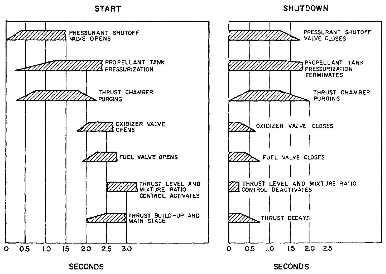 Figure 3-11.-A-4 stage engine operational sequence.
2.9 Tax TV⿻十⺀大]
