1.3 PERFORMANCE PARAMETERS OF A LIQUID PROPELLANT ROCKET ENGINE
The performance of a rocket engine is expressed by a quantity commonly called "specific impulse," . If impulse imparted to the vehicle and propellant weight consumption were measured during a given time interval, would have the dimension . In practice, thrust is usually measured, in conjunction with propellant weight flow-rate measurements. This yields the same dimension: . may thus be expressed as
Since weight is the force exerted by a mass on its rigid support under the influence of gravitation (by convention at sea level on Earth), it has become accepted practice to measure in "seconds," by canceling out the terms for the forces. Obviously, the expression does not denote a time, but rather a magnitude akin to efficiency. directly contributes to the final velocity of the vehicle at burnout and thus has a pronounced effect on range or size of payload, or both. This will be shown further below in connection with equation (1-30).
It is important to state whether a specific impulse quoted refers to the thrust chamber assembly only , or to the overall engine system ( . Often, the distinction may not be selfevident. It is important, therefore, to state accurately to what system the quoted specific impulse refers. For instance, in a turbopump fed system, overall engine specific impulse may include turbine power requirements, vernier, and attitude control devices. All of these may be fed from one or all of a given vehicle's propellant tanks. If they are properly considered, the user, in this case the vehicle builder, will obtain the correct value for his own optimization studies, which include propellant tank sizes, payload weight, and range, among other parameters.
In many instances, statement of the specific impulse for the thrust chamber only may be desirable, such as during the component development period of this subassembly. Since, in that case, those propellant demands which are inadequately or not at all contributing to the generation of thrust are not included, the specific impulse stated will be higher than for a complete system, by 1 to 2 percent, as a rule. The specific impulse thus stated would be too high for the vehicle builder, who must consider the supply of propellants to the auxiliary devices mentioned above as well. If, due to improper identification of , a thrust chamber value were used as an engine value, the consequences would be serious. This becomes clear, if one realizes that when relying on a better-than-actual value, propellant tank sizes would be designed too small, resulting in premature propellant depletion. This would eliminate the last seconds of required burning time, when the vehicle mass being accelerated is near empty weight and acceleration, therefore, is near maximum. A substantial loss of range for a given payload would result. The situation would be further complicated by the fact that it is nearly impossible to improve the specific impulse once an engine and thrust chamber have been designed, for a given propellant combination.
Another important performance parameter is the propellant mass fraction of the complete vehicle, of which the engine system is a part. The propellant mass fraction is defined as
where the initial rocket mass is equal to the sum of the masses of the engine system at burnout, the structure and guidance system, the payload, and the propellant. The significance of the propellant mass fraction can be illustrated by the basic equation for the rocket burnout velocity
where the coefficient corrects for the effects of aerodynamic and gravitational forces. It is composed of several parameters which vary with type of trajectory and with elapsed time during flight. Although they are of no concern here, they are of great importance to the vehicle builder. Also, they cannot be neglected for rigorous engine design analyses which must include trajectory information.
Thrust Chamber Specific Impulse
The overall performance of the liquid propellant thrust chamber is a direct function of the propellant combination, the combustion efficiency of propellants in the chamber, and the product gas expansion performance in the nozzle. The expression for may be obtained in several ways:
From equation 1-28:
Combine equations 1-31 and 1-7:
The effective exhaust velocity may be further defined as the product of two convenient parameters, and
where the characteristic velocity c* in feet per second (commonly pronounced "cee-star") is a parameter primarily used to rate the propellant combustion performance. The thrust coefficient is a dimensionless parameter used to measure the gas expansion performance through the nozzle. Combine equations 1-31a and 1-31b:
While and are of ultimate importance to the missile or space vehicle builder, both and are of great and early importance to the engine and thrust chamber designer and developer.
Characteristic Velocity c*
In a system with sonic velocity at the throat, the quantity reflects the effective energy level of the propellants and the design quality of injector and combustion chamber. It may be defined by the following expression:
This form shows that * measures combustion performance in a given combustion chamber by indicating how many pounds per second of propellant must be burned to maintain the required nozzle stagnation pressure. A lower value of propellant consumption under the given condition indicates a combustion process of higher energy and efficiency and gives a corresponding higher value of . By substituting with equation 1-19 in equation 1-32, the equation for theoretical may be rewritten in the following form:
This form shows that is a function of the properties of the combustion product gas at the exit of the combustion chamber, i.e., at the nozzle inlet; namely, specific heat ratio , gas constant , and temperature .
Thrust Coefficient
The quantity reflects the product gas expansion properties and design quality of the nozzle. Combining equations 1-31, 1-31c, and 1-32, the expression for theoretical may be written as:
This form shows that measures the force augmented by the gas expansion through the nozzle as compared with the force which would be generated if the chamber pressure acted over the throat area only. By combining equations , 1-18, 1-19, and 1-33, the equation for theoretical at any altitude may be rewritten in the following form:
Equation 1-33a shows that is a function of specific heat ratio , chamber pressure , ambient pressure , and the nozzle area expansion ratio .
As will be noted, the throat stagnation pressure has been used in equations (1-32) and (1-33). This has been the practice in industry and in most of the literature. Briefly, the reason is that reflects the true theoretical gas property at combustion chamber exit, i.e., at the nozzle inlet, and gives a more logical value to and . In actual operation the true value of cannot be measured. is mathematically converted from the measured value of the gas static pressure at the injector, . The accuracy of this calculated value has to be verified by the test results. Likewise, the gas properties, and thus the specific heat ratio which additionally changes along the chamber axis, affect the true values of and . This will have to be verified by actual test results.
To understand better the nature of and the design parameters which influence it, let us first rearrange equation (1-33):
The formula expresses that the thrust generated by a thrust chamber (the effect) is produced by pressure (the cause) as a function of the physical properties of the chamber itself. The relationships and effects of the principal design parameters become clearer if we proceed in steps as follows:
Assume we wish to generate a certain thrust . Our chamber is a straight cylinder (fig. 1-7). The pressure in this chamber has a very small effect on the cylindrical wall (the forces normal to the chamber axis will cancel each other), except for effects of friction, which we will neglect. There is no part of the chamber for the pressure to act upon at the exit. The only chamber area upon which the pressure can act is the injector plate. Since, for the cylindrical chamber, the injector area is equal to , we can write:
For the reasons explained above, we rewrite to include :
Since is smaller than (fig. 1-4), the
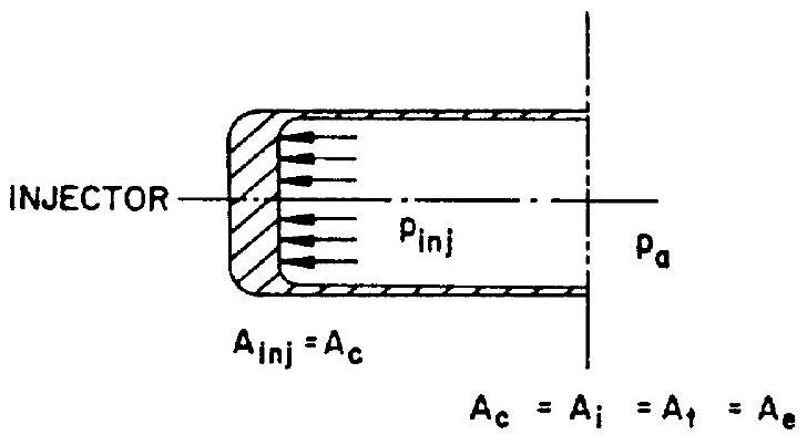 Figure 1-7
coefficient is introduced to correct for this fact. For instance, if the ratio was found to be 0.8 from figure would have to be 1.25 to offset the introduction of . As will be seen, the use of a thrust coefficient of 1.25 , for instance, in a straight cylinder thrust chamber for which is 0.8 , is merely part of a mathematical rearrangement, but does not signify an increase in thrust for a given Pinj.
It is noted that the combustion chamber including injector will have to produce the required pressure with a flow rate, the magnitude of which is determined by and by the throat area . Transformation of equation (1-32) shows the relationship:
In actual practice, the value of for a given propellant combination and thrust chamber design is arrived at tentatively from existing experience and is subsequently refined during development testing.
Let us now redesign our cylindrical thrust chamber, as shown in figure 1-8. Maintaining the same throat area , we enlarge the combustion chamber including injector to a diameter somewhat larger than that of . The flow rate remains
In the straight cylindrical chamber (fig. 1-7), the gas velocity was sonic at the end of the cylindrical chamber portion, which coincided with and . From earlier discussions (see sec. 1-2), we know that expansion (acceleration) is nonisentropic in that case. In the redesigned chamber (fig. 1-8) by contrast, gas velocities are still well below sonic velocity at the end of the cylindrical portion. Most of the acceleration to sonic velocity will now occur in the added, convergent nozzle. Since we can make the assumption, which is essentially correct, that the combustion process is complete at the end of the cylindrical chamber portion, the subsequent expansion (acceleration) in the convergent nozzle is assumed to be isentropic; i.e., to occur without further total pressure losses. Since we keep and constant, and assume that remains unchanged, the nozzle stagnation pressure , too, will retain the same value as in
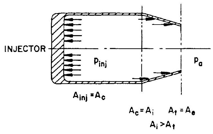 Figure 1-8
the case of the straight cylindrical chamber. However, because of the reduced pressure losses in the combustion chamber, the required total pressure at the injector end will definitely be lower.
The redesign, then, has the favorable result that, for instance, in pressurized systems, the same propellant flow rate can be sustained with lower tank pressures, thus, slightly lighter tanks can be used. In turbopump-fed systems, required turbopump horsepower will decrease. However, the forces acting upon the thrust chamber, and thus the developed thrust, can be assumed to have remained unchanged, since a lower pressure acts upon the larger injector, and since opposing forces are present at the converging nozzle.
In short, it may be stated that our redesign (fig. 1-8) results in reduced demands on the propellant feed system for the same and the same thrust level.
We now proceed to further redesign the chamber to include a divergent nozzle section, as in figure 1-9. Up to the throat area, nothing changes over the preceding configuration, which includes a convergent nozzle only. Since the gas velocity in the throat area is always sonic (except for very low, subcritical chamber pressures), the attachment of the divergent nozzle section, likewise, will have no effect on the previously described gas processes and the pressures upstream of the throat. However, conditions downstream from the throat are now different.
With the cylindrical chamber, and the chamber with convergent nozzle, the static pressure energy available at the throat is dissipated by
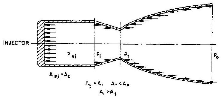 Figure 1-9
expansion to atmospheric pressure, flowing freely in all directions. By attaching a divergent nozzle, we prevent the gases from dissipating at random, and further accelerate the gases in one preferred direction only. Since this process takes place in the divergent part of the thrust chamber, the static pressures of the expanding gases produce a force on the chamber, as indicated by the arrows in figure 1-9. The expression of the thrust for the complete thrust chamber with convergent-divergent nozzle can now be written as:
The last expression in the equation represents the gain realized from attaching the divergent nozzle to the throat. By combining all gains into a single coefficient (see eq. 1-33), we arrive again at equation (1-34):
In brief, it may be stated that the redesign (fig. 1-9) results in an increased thrust level, for the same and the same feed system configuration.
Summary of the Influences of , and on Engine Performance
The Effect of
An ambient pressure reduces the vacuum thrust of an engine by the amount . (See eq. (1-6).) is similarly affected by the amount , as shown in equation 1-33a). This may be rewritten as . The lower the ambient pressure, the higher thrust and performance. Maximum values are obtained in vacuum.
The Effect of
Optimum thrust for a given ambient pressure is obtained when the nozzle expansion area ratio is such that . This may be seen from figure 1-10. If the divergent nozzle section is extended in the region where , thrust will increase. Where , however, lengthening of the nozzle will decrease thrust. Hence it would be beneficial to design the nozzle to yield , to reach an optimum value for the thrust coefficient. The for this condition is called optimum nozzle expansion area ratio. Unfortunately, because of changing ambient pressure during flight, no one single is optimum. Optimization studies are usually made to determine the best compromise. Such a study is not required (except for weight and size considerations) for rockets which start and stop at the same ambient pressure, such as upper stages, where ambient pressure is zero or near zero at all times. For the special case of (vacuum conditions), would become infinity, to satisfy "ideal expansion." Even for this case, however, expansion ratios over 25 contribute little. The nozzle design is usually "cut" at this point, mainly for weight considerations. This leaves a small positive pressure at the exit which is unavailable for final gas acceleration. However, it still contributes as a positive term .
The Effect of
The specific heat ratio is an indication of the energy storing capacity of the gas molecule. A smaller value of indicates a higher energystoring capability, and in turn gives higher engine performance. As shown in equations (1-32a) and (1-33a), a smaller will yield a higher value for both, and . The influence of the properties of the selected propellants and of the combustion products is apparent.
The Effect of
It can be seen from equation (1-32) that for constant will increase if the gas
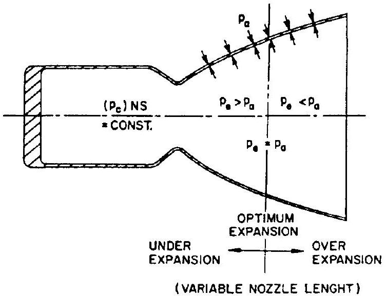 Figure 1-10
constant increases; i.e., the gas molecular weight decreases. Thus, a higher value of will yield a higher engine performance.
The Effect of
The effective chamber pressure or nozzle stagnation pressure appears in equation (1-33a) for in the form of two pressure ratios and . As is evident from equation (1-20), the ratio has a singular value, for a given and in equation (1-33), therefore, influences only through the negative term . An increase in decreases this negative term and hence increases . This effect is more pronounced when is high. Since the thrust is proportional to both and , we see now clearly how an increase in in a given thrust chamber will increase the thrust. also has some effect on the combustion process. Increasing tends to increase and to reduce and . The overall result is usually an increase in . However, these effects are slight, especially at above 300 psi .
Correction Factors and Magnitudes of Engine Performance Parameters
The actual performance of a liquid propellant rocket engine differs from that of an ideal one because of friction effects, heat transfer, nonperfect gases, nonaxial flow, nonuniformity of working substance and of flow distribution, and shifting gas composition. The latter refers to the fact that the gas properties ( , II, ) are not truly constant along the nozzle axis, as the isentropic treatment of the processes assumes. Therefore, correction factors have to be applied to the performance parameters which are derived from theoretical assumptions. Following are some important correction factors:
Correction factor for thrust and thrust coefficient
The values for range from 0.92 to 1.00 . Correction factor for effective exhaust velocity and specific impulse
The values for range from 0.85 to 0.98 . Correction factor for characteristic velocity
The values for range from 0.87 to 1.03 . Correction factor for propellant mass flow rate
The values for range from 0.98 to 1.15 . The relation between correction factors may be expressed as:
Actual ranges of liquid propellant rocket engine parameters are listed in table 1-3.
TABLE 1-3
| Gas temperature, T. | to |
|---|---|
| Nozzle stagnation pressure | 10 to 2500 psia |
| Molecular weight, III | 2 to 30 |
| Gas constant, . | 51.5 to 772 |
| Gas flow Mach number, M | 0 to 4.5 |
| Specific heat ratio. r | 1.13 to 1.66 |
| Nozzle expansion area ratio. 6 | 3.5 to 100 |
| Nozzle contraction area ratio, | 1.3 to 6 |
| Thrust coefficient, | 1.3 to 2.0 |
| Characteristic velocity, | 3000 to |
| Effective exhaust velocity, | 4000 to |
| Specific impulse, | 150 to 480 sec (vacuum) |
Values of the vacuum or altitude thrust coefficient plotted as functions of nozzle expansion area ratio and gas specific heat ratio are shown in figure 1-11.
Sample Calculation (1-3)
Assume a thrust chamber for the same ideal liquid propellant rocket engine as given in sample calculation (1-2), in which ; ; .
Determine the following: (a) Theoretical ; (b) theoretical at sea level and in space; (c) theoretical at sea level and in space; (d) actual , if correction factor ; (e) actual at sea level and in space, if sea level correction factor: ; (f) actual at sea level and in space; correction factor at sea level; (h) thrust at sea level and in space; (i) actual and .
Solution
(a) From equation (1-32a):
(b) From equation (1-33a):
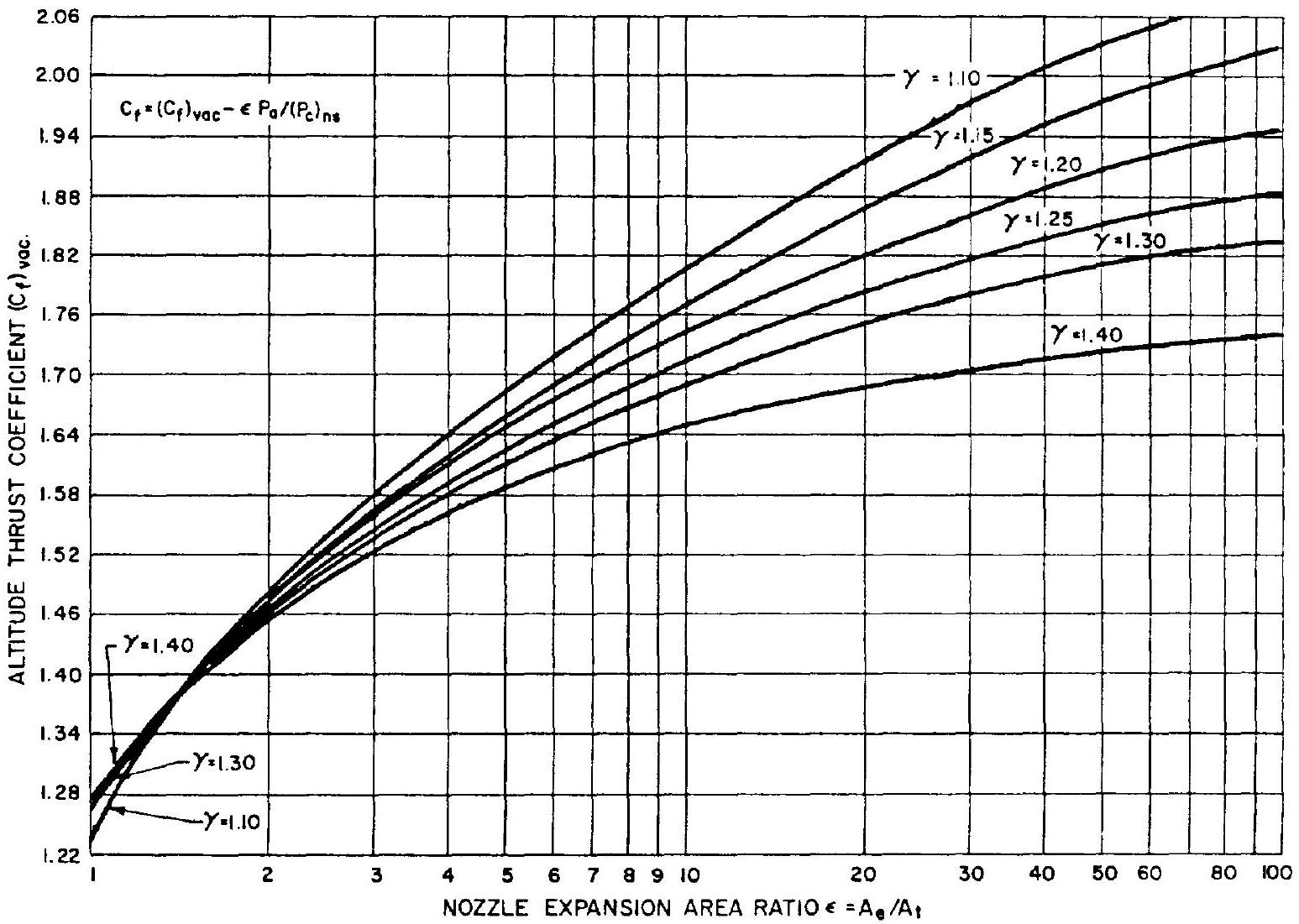 Figure 1-11.-Altitude thrust coefficient as function of area ratio and specific heat ratio.
Theoretical
From sample calculation (1-2)
At sea level : Theoretical
In space: Theoretical
(c) From equation (1-31):
At sea level: Theoretical
In space:
Theoretical (d) From equation (1-41):
Actual theoretical
(e) From equation (1-39):
Actual .theoretical At sea level:
Actual
In space: Actual
(f) At sea level:
Actual
In space: Actual (g) From equation (1-40):
Or from equation (1-43):
(h) From equation (1-31):
Thrust at sea level at sea level
Thrust in space in space
(i) From equation (1-33):